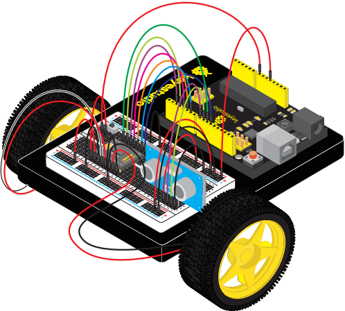
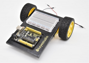
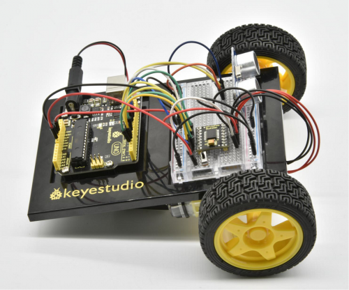
Ks0436 keyestudio Ultimate Starter Kit For Little Inventor (Zero-based Arduino Learning Robot)
WELCOME TO THE KIT GUIDE
This is your map for navigating beginning embedded electronics.
This kit contains all the information you will need to build the circuit and robot projects for the keyestudio REV4 Board.
When you’re done with this guide, you will have built five great projects and acquired the know-how to create countless more.
Now enough talk — let’s start something!
INTRODUCTION
The REV4 Board Platform
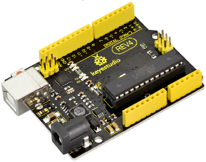
The keyestudio REV4 Board is your development platform.
The REV4 Board is essentially a small, portable computer, also known as a microcontroller.
It is capable of taking inputs (such as the push of a button or a reading from a light sensor) and interpreting that information to control various outputs (like blinking an LED light or spinning an electric motor).
This board is capable of taking the world of electronics and relating it to the physical world in a real and tangible way.
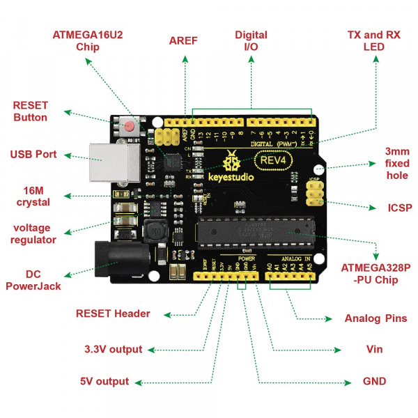
The keyestudio REV4 Board is a microcontroller board based on the ATmega328P microprocessor.
It has 14 digital input/output pins (of which 6 can be used as PWM outputs), 6 analog inputs, a 16 MHz quartz crystal, a USB connection, a power jack, 2 ICSP headers and a reset button.
It contains everything needed to support the microcontroller; simply connect it to a computer with a USB cable or power it via an external DC power jack (DC 7-12V) or via female headers Vin/GND(DC 7-12V) to get started.
The Breadboard Platform
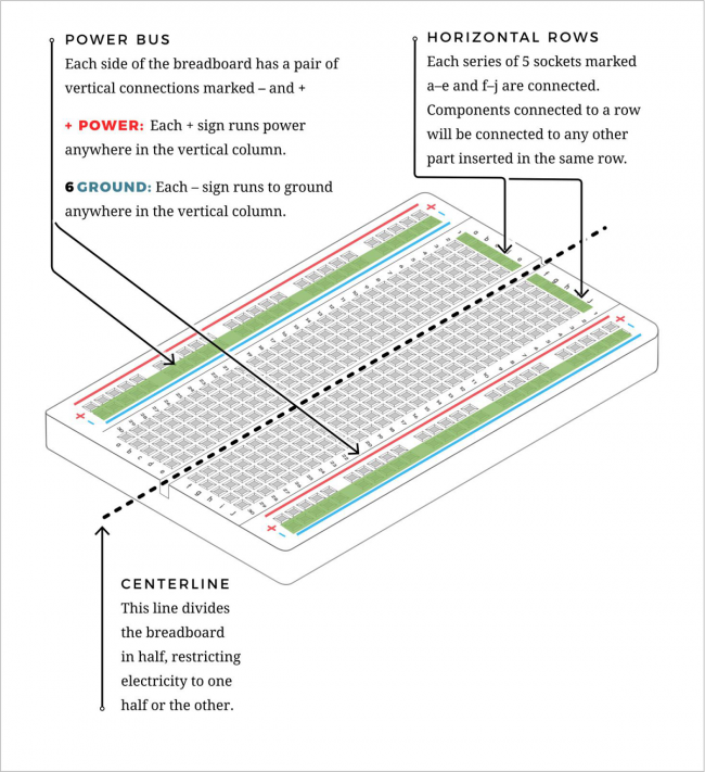
A breadboard is a circuit-building platform that allows you to connect multiple components without using a soldering iron.
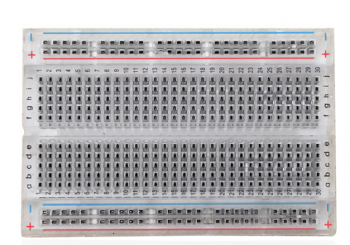
This is a half-size transparent breadboard, good for small projects.
It has 2 power rails on both sides, a standard double-strip in the middle with 30 columns and 10 rows - a total of 400 tie in points.
This tiny breadboard also has a self-adhesive on the back, so you can stick it onto an Arduino protoshield or keyestudio chassis.
The Baseplate Assembly
Before you can build circuits, you’ll want to first assemble the breadboard baseplate.
This keyestudio baseplate makes circuit building easier by keeping the REV4 Board microcontroller and the breadboard connected without the worry of disconnecting or damaging your circuit.
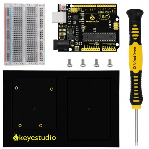
1)To begin with, collect your parts: the REV4 Board, breadboard, screwdriver, keyestudio baseplate and four baseplate screws.
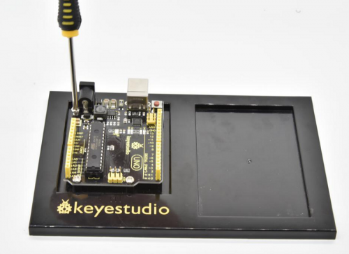
2)Align the REV4 board with its spot on the baseplate.
The text on it should face the same direction as the text on the breadboard and the baseplate.
Using four screws, affix the REV4 Board to the four stand-off holes found on the baseplate.
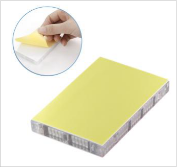
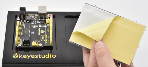
3)Peel the adhesive backing off the breadboard.
4)Carefully align the breadboard over its spot on the baseplate. The text on the breadboard should face the same direction as the text on the baseplate. Firmly press the breadboard to the baseplate to adhere it.
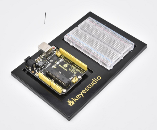
Your baseplate is now assembled!
The Arduino IDE
In order to get your REV4 Board up and running.
you'll need to download the newest version of the Arduino software from www.arduino.cc (it's free!).

This software, known as the Arduino IDE (Integrated Development Environment), will allow you to program the REV4 Board to do exactly what you want. It’s like a word processor for coding.
With an internet-capable computer, open up your favorite browser and type the following URL into the address bar to download the software of any versions:
https://www.arduino.cc/en/Main/OldSoftwareReleases#1.5.x
Open Arduino IDE
Downloaded the software package, unzip the folder package, double click the Arduino icon to open.

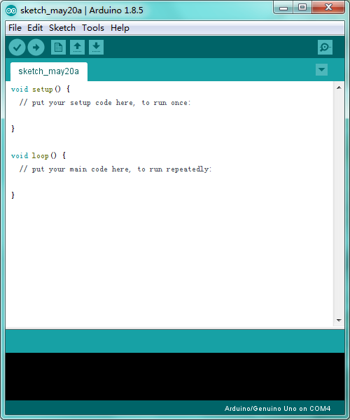
The functions of each button on the Toolbar are listed below:
![]()
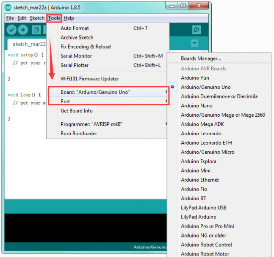
Select Your Board And Serial Port
NOTE: select the Arduino UNO, but if you are not sure which ports should choose. Go to your computer panel, and check the Port out in the Device Manger.
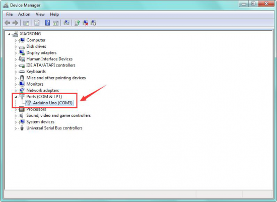
The Parts List
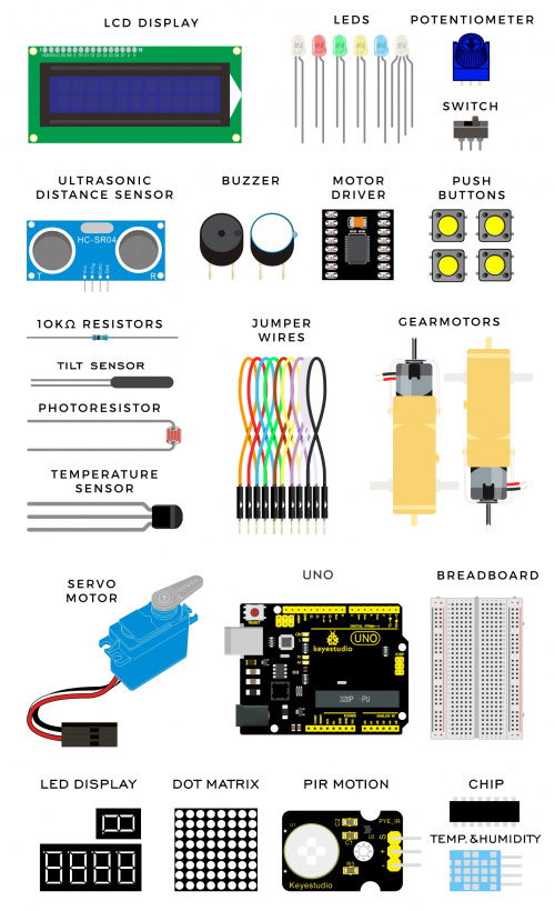
The Kit contains extensive electronic components. Below shows you a part of kit components:
GET STARTED WITH CIRCUIT PROJECTS!
There are 20 circuit projects total. Each project will introduce new concepts and components, which will be described in more detail as you progress through the circuits.
As you work your way through each circuit, you will learn to use new and more complicated parts to accomplish increasingly complex tasks.
The project will set the foundation for the rest and will aid in helping you understand the fundamentals of circuit building and electricity!
Circuit 1: Blinking an LED
About this circuit:
Blinking an LED is the classic starting point for learning how to program embedded electronic components.
In this circuit, you’ll write code that makes an LED blink on and off.
What You Need:
- REV4 Baseplate
- Red LED x 1
- 220Ω Resistor x 1
- Jumper wires x 2
- USB cable x 1
Component Introduction:
LIGHT-EMITTING DIODES (LEDS):
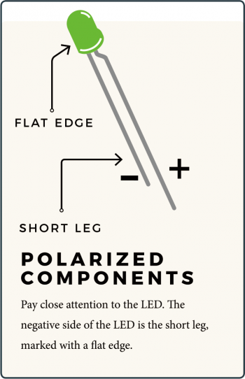
They come in different colors, brightnesses and sizes. LEDs have a positive (+) leg and a negative (-) leg, and they will only let electricity flow through them in one direction.
LEDs can also burn out if too much electricity flows through them, so you should always use a resistor to limit the current when you wire an LED into a circuit.
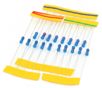
RESISTORS: resist the flow of electricity.
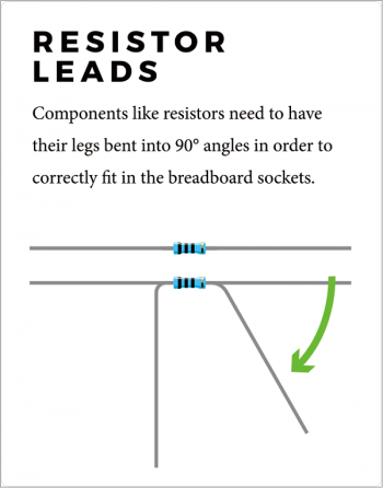
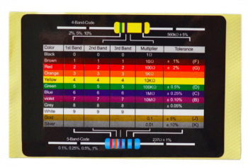
You can use them to protect sensitive components like LEDs. The strength of a resistor (measured in ohms) is marked on the body of the resistor using small colored bands.
Each color stands for a number, which you can look up using a resistor chart.
Wiring Diagram:
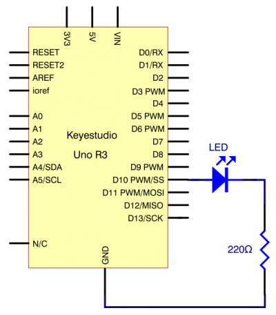
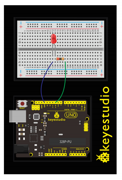
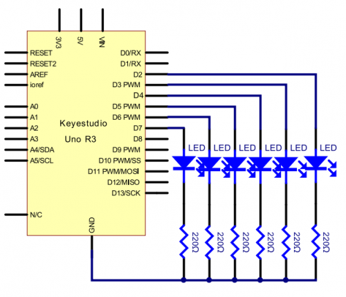
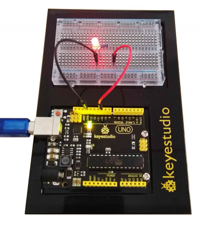
Check out the schematics and wiring diagram below to see how everything is connected.
With the 220Ω resistor in place, the LED should be quite bright.
If you swap out the 220Ω resistor for the 1kΩ resistor, then the LED will appear a little dimmer.
At the moment, you have Digital pin 10 going to one leg of the resistor, the other leg of the resistor going to the positive side of the LED and the other side of the LED going to GND.
Upload Code:
- 1)Connect the REV4 Board to a USB port on your computer.
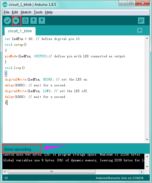
- 2)Open the program in the code folder- Circuit 1 LED, or directly copy and paste the code below on the Ardunio IDE.
- 3)Select UPLOAD to program the sketch on the REV4 Board.
int ledPin = 10; // define digital pin 10.
void setup()
{
pinMode(ledPin, OUTPUT);// define pin with LED connected as output.
}
void loop()
{
digitalWrite(ledPin, HIGH); // set the LED on.
delay(1000); // wait for a second.
digitalWrite(ledPin, LOW); // set the LED off.
delay(1000); // wait for a second
}
Code Explanation:
- Single line comments start with // and everything up until the end of that line is considered a comment.
Comments are a great way to leave notes in your code explaining why you wrote it the way you did.
- The first line of code is:
int ledPin = 10; // define digital pin 10
As the comment above it explains, this is giving a name to the pin that the LED is connected to. You can change the connection pin here.
- Next, we have the “setup” and “loop” function
void setup()
Every Arduino sketch must have a 'setup' function, and the place where you might want to add instructions of your own is between the { and the }.
In this case, there is just one command there, which, as the comment states tells the Arduino board that we are going to use the LED pin as an output.
void loop()
It is also mandatory for a sketch to have a “loop” function. Unlike the 'setup' function that only runs once, after a reset, the 'loop' function will, after it has finished running its commands, immediately start again.
- Input Or Output ?:
pinMode(ledPin, OUTPUT)
Before you can use one of the digital pins, you need to tell the REV4 Board whether it is an INPUT or OUTPUT.
We use a built-in “function” called pinMode() to make pin 10 a digital output.
Digital Output:
digitalWrite(ledPin, HIGH)
digitalWrite(ledPin, LOW)
When you’re using a pin as an OUTPUT, you can command it to be HIGH (output 5 volts) or LOW (output 0 volts).
- What happens when you change the number in one or both of the delay(1000)
This delay period is in milliseconds, so if you want the LED to blink twice as fast, change the value, try 500 or 2000.
Upload the sketch again and you should see the LED start to blink more quickly or slowly.
After downloading this program, in the experiment, you will see the LED flashing on for one second, then off for one second.
The blinking LED experiment is now completed. Thank you!
Troubleshooting:
- Upload failed?
Make sure you have assembled the circuit correctly and verified and uploaded the code to your board. Check out the Board and Serial Port.
Circuit 2: Light Extension
About this circuit:
After mastering LED Blinking, let’s move on to how to control lots of LEDs. The principle is almost the same.
In this circuit, you’ll write code that makes six LEDs blink on and off one by one.
Furthermore, you can also use three LEDs to simulate the traffic light. Now let’s start something different!
What You Need:
- REV4 Baseplate
- Red LED x 6
- 220Ω Resistor x 6
- Jumper wires x 7
- USB cable x 1
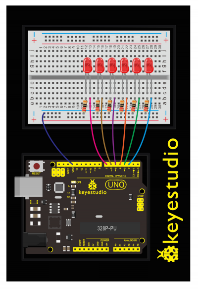
Wiring Diagram:
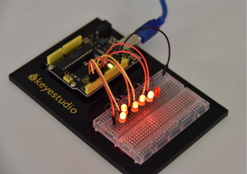
Check out the wiring below to see how everything is connected.
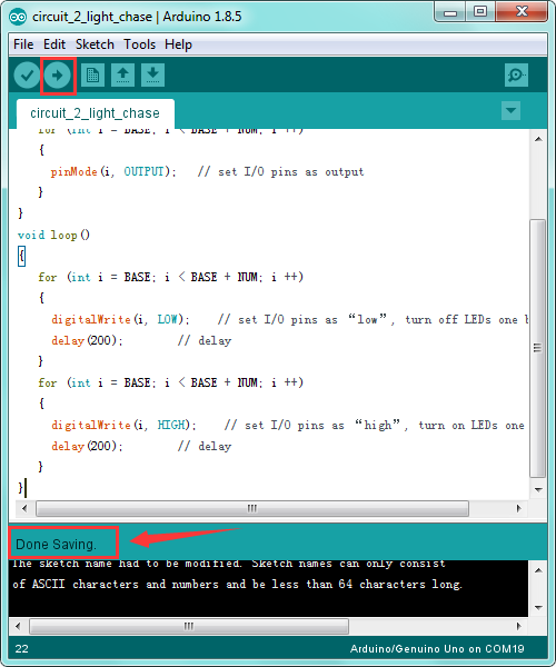
Upload Code:
- 1)Connect the REV4 Board to a USB port on your computer.
- 2)Open the program in the code folder- Circuit 2 Light, or directly copy and paste the code below on the Ardunio IDE.
- 3)Select UPLOAD to program the sketch on the REV4 Board.
int BASE = 2 ;  // the I/O pin for the first LED
int NUM = 6;   // the number of LEDs
void setup()
{
   for (int i = BASE; i < BASE + NUM; i ++)
   {
     pinMode(i, OUTPUT);   // set I/O pins as output
   }
}
void loop()
{
   for (int i = BASE; i < BASE + NUM; i ++)
   {
     digitalWrite(i, LOW);    // set I/O pins as “low”, turn off LEDs one by one.
     delay(200);        // delay
   }
   for (int i = BASE; i < BASE + NUM; i ++)
   {
     digitalWrite(i, HIGH);    // set I/O pins as “high”, turn on LEDs one by one
     delay(200);        // delay
   }
}
Code Explanation:
- Single line comments start with // and everything up until the end of that line is considered a comment.
Comments are a great way to leave notes in your code explaining why you wrote it the way you did.
- int BASE = 2 ; // set the I/O pin for the first LED
- int NUM = 6; // the number of LEDs
You can see the six LEDs blink on and off one by one. It seems like light chasing.
If it doesn’t, make sure you have assembled the circuit correctly and verified and uploaded the code to your board.
Check out the Board and Serial Port.
Troubleshooting:
- Upload failed?
Make sure you have assembled the circuit correctly and verified and uploaded the code to your board. Check out the Board and Serial Port.
- LED Not Lighting Up?
Make sure you connect the LED correctly or try other LEDs.
How to make traffic light?
What You Need:
- REV4 Baseplate
- Red LED x 1
- Yellow LED x 1
- Green LED x 1
- 220Ω Resistor x 3
- Jumper wires x 4
- USB cable x 1
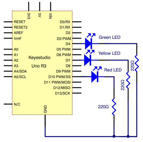
Hookup Guide:
Check out the hookup table below to see how everything is connected.
Schematics:
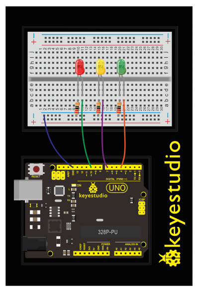
Source Code:
int redled =10; // initialize digital pin 8.
int yellowled =7; // initialize digital pin 7.
int greenled =4; // initialize digital pin 4.
void setup()
{
pinMode(redled, OUTPUT);// set the pin with red LED as “output”
pinMode(yellowled, OUTPUT); // set the pin with yellow LED as “output”
pinMode(greenled, OUTPUT); // set the pin with green LED as “output”
}
void loop()
{
digitalWrite(greenled, HIGH);//// turn on green LED
delay(5000);// wait 5 seconds
digitalWrite(greenled, LOW); // turn off green LED
for(int i=0;i<3;i++)// blinks for 3 times
{
delay(500);// wait 0.5 second
digitalWrite(yellowled, HIGH);// turn on yellow LED
delay(500);// wait 0.5 second
digitalWrite(yellowled, LOW);// turn off yellow LED
}
delay(500);// wait 0.5 second
digitalWrite(redled, HIGH);// turn on red LED
delay(5000);// wait 5 second
digitalWrite(redled, LOW);// turn off red LED
}
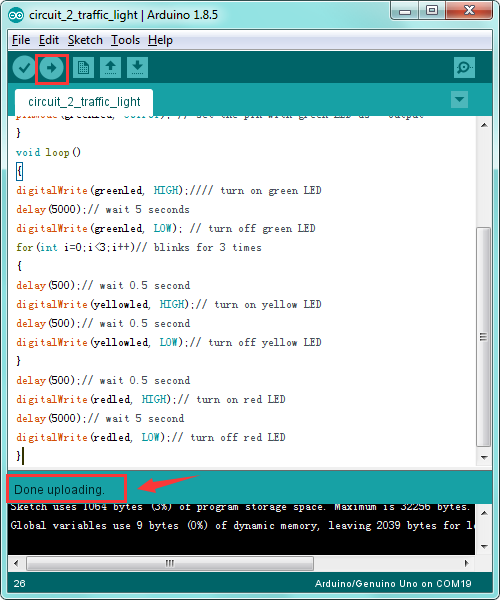
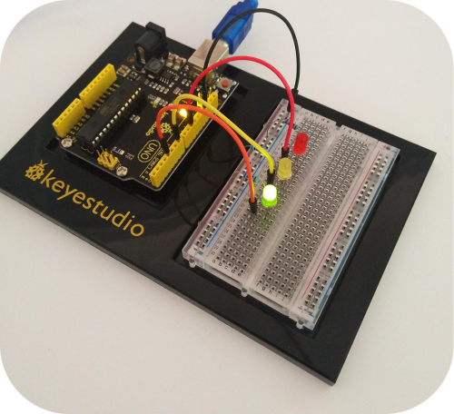
Done uploading the code, you can see your own designed traffic light.
This circuit design is very similar with the one in LED chase effect.
The green light will turn on for 5 seconds, and then off, followed by the yellow light blinking for 3 times, and then red light turns on for 5 seconds, circularly and repeatedly.
Circuit 3: Potentiometer
About this circuit:
In the previous project, you have learned how to turn on or off an LED.
In this circuit, you’ll use a potentiometer as an input device to control the speed at which your LED blinks.
Here may involves a new concept PWM to control the brightness of an LED. Check more details below.
What You Need:
- REV4 Baseplate
- Potentiometer x 1
- Red LED x 1
- 220Ω Resistor x 1
- Jumper wires x 6
- USB cable x 1
Component Introduction:
POTENTIOMETER:
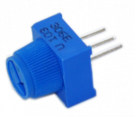
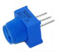
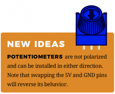
Potentiometers (also known as“trimpots”or“knobs”) are one of the basic inputs for electronic devices.
A potentiometer is a 3-pin variable resistor.
When powered with 5V, the middle pin outputs a voltage between 0V and 5V, depending on the position of the knob on the potentiometer.
By tracking the position of the knob with your REV4 Board, you can make volume controls, speed controls, angle sensors and a ton of other useful inputs for your projects.
PWM Control:
PWM is short for Pulse Width Modulation.
Pulse Width Modulation, or PWM, is a technique for getting analog results with digital means.
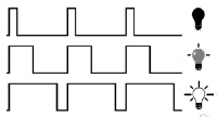
Digital control is used to create a square wave of different duty cycle, a signal switched between on and off. This on-off pattern can simulate voltages in between full on (5 Volts) and off (0 Volts) by changing the portion of the time the signal spends on versus the time that the signal spends off.
In the graphic, the green lines represent a regular time period.
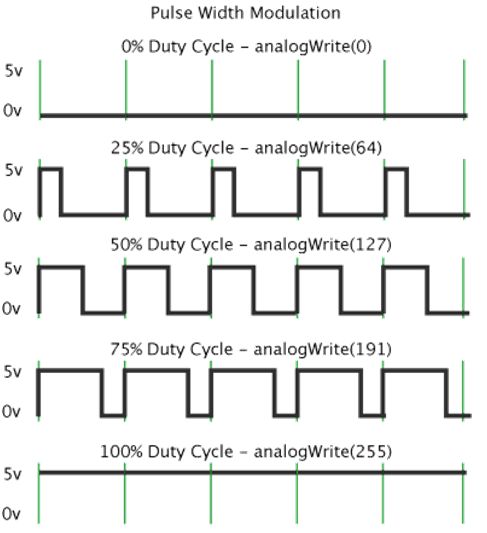
This duration or period is the inverse of the PWM frequency.
In other words, with Arduino's PWM frequency at about 500Hz, the green lines would measure 2 milliseconds each.
A call to analogWrite() is on a scale of 0-255, such that analogWrite(255) requests a 100% duty cycle (always on), and analogWrite(127) is a 50% duty cycle (on half the time) for example.
To be simply, we all know that the voltage output of Arduino Digital port only has two states, LOW and HIGH, corresponding to the voltage output of 0V and 5V.
If merely make use of LOW and HIGH state, it cannot control the brightness of an LED light. However, if convert the voltage output of 0 Volts and 5 Volts into the value within 0-255, this way you can change the value within 0-255 to control the brightness of light.
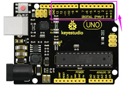
The Arduino controller has totally 6 PWM outputs, which are Digital 3, 5, 6, 9, 10 and 11.
These pins can be used as Digital output or Analog output. If used as Analog output, it needs to call the analogWrite() function of ARDUINO, and this analogWrite() function can be controlled in the range of 0-255.
Hookup Guide:
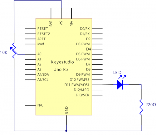
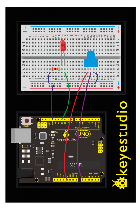
The input of potentiometer is analog, so we connect it to analog port, and LED to PWM pin.
Different PWM signals can regulate the LED brightness.
Upload Code:
- 1)Connect the REV4 Board to a USB port on your computer.
- 2)Open the program in the code folder- Circuit 3 Potentiometer, or directly copy and paste the code below on the Ardunio IDE.
- 3)Select UPLOAD to program the sketch on the REV4 Board.
int potpin=0;// initialize analog pin 0
int ledpin=11;//initialize digital pin 11(PWM output)
int val=0;// Temporarily store variables' value from the sensor
void setup()
{
pinMode(ledpin,OUTPUT);// define digital pin 11 as “output”
Serial.begin(9600);// set baud rate at 9600
// attention: for analog ports, they are automatically set up as “input”
}
void loop()
{
val=analogRead(potpin);// read the analog value from the sensor and assign it to val
Serial.println(val);// display value of val
analogWrite(ledpin,val/4);// turn on LED and set up brightness(maximum output of PWM is 255)
delay(10);// wait for 0.01 second
}
Code Explanation:
- Single line comments start with // and everything up until the end of that line is considered a comment.
Comments are a great way to leave notes in your code explaining why you wrote it the way you did.
- The first line of code is:
int potpin=0;// initialize analog pin 0
A variable is a placeholder for values that may change in your code. You must introduce, or“declare,”variables before you use them.
Here we’re declaring a variable called potPosition of type int (integer).
- Serial.begin(9600)
Serial commands can be used to send and receive data from your computer. Notice that the baud rate, 9600, is the same as the one we selected in the monitor. This is the speed at which the two devices communicate, and it must match on both sides.
- val=analogRead(potpin)
We use the analogRead() function to read the value on an analog pin.
- Serial.println(val);
This is the line that actually prints the trimpot value to the monitor.
What You Will See:
You should see the LED brighter or dim in accordance with your potentiometer.
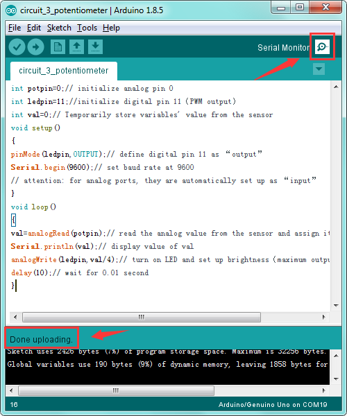
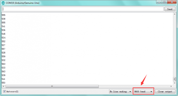
You should see numeric values print out in the monitor. Turning the potentiometer changes the value.
Troubleshooting:
- Upload failed?
Make sure you have assembled the circuit correctly and verified and uploaded the code to your board. Ensure that you are on the correct Board and Serial Port.
- No values in Serial Monitor?
Make sure that you have selected the correct baud rate, 9600.
Circuit 4: Photo Resistor
About this circuit:
In the previous circuit, you have learned how to use a potentiometer as an input device to control the LED’s brightness.
In this circuit, you’ll be using a photoresistor, which changes resistance based on how much light the sensor receives.
Using this sensor you can make a simple night-light that turns on when the room gets dark and turns off when it is bright.
What You Need:
- REV4 Baseplate
- Potentiometer x 1
- Red LED x 1
- 220Ω Resistor x 1
- 10KΩ Resistor x 1
- Jumper wires x 5
- USB cable x 1
Component Introduction:
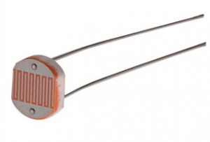
Photo Resistor:
Photo resistor (Photovaristor) is a resistor whose resistance varies according to different incident light strength.
It's made based on the photoelectric effect of semiconductor.
If the incident light is intense, its resistance reduces; if the incident light is weak, the resistance increases.
Photo resistor is widely applied to various light control circuit, such as light control and adjustment, optical switches, etc.
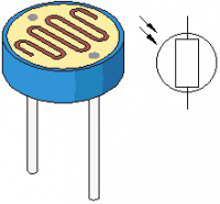
Photovaristor is an element that changes its resistance as light strength changes. So we will need to read the analog values.
We can refer to the PWM experiment, replacing the potentiometer with photovaristor. When there is change in light strength, there will be corresponding change on the LED.
Hookup Guide:
The photoresistors, like regular resistors, are not polarized and can be installed in either direction.
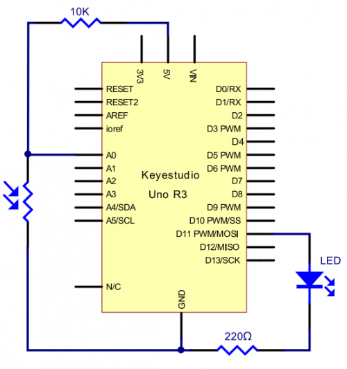
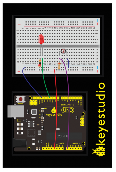
Upload Code:
- 1)Connect the REV4 Board to a USB port on your computer.
- 2)Open the program in the code folder- Circuit 4 Photoresistor, or directly copy and paste the code below on the Ardunio IDE.
- 3)Select UPLOAD to program the sketch on the REV4 Board.
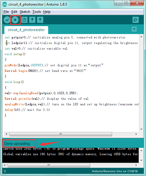
After the connection, let's begin the program compiling. The program is similar to the one of PWM.
For change details, please refer to the Sample Code below.
int potpin=0;// initialize analog pin 0, connected with photovaristor
int ledpin=11;// initialize digital pin 11, output regulating the brightness of LED
int val=0;// initialize variable val
void setup()
{
pinMode(ledpin,OUTPUT);// set digital pin 11 as“output”
Serial.begin(9600);// set baud rate at“9600”
}
void loop()
{
val= map(analogRead(potpin),0,1023,0,255);
Serial.println(val);// display the value of val
analogWrite(ledpin,val);// turn on the LED and set up brightness(maximum output value 255)
delay(10);// wait for 0.01
}
What You Will See:
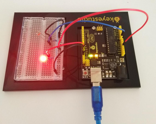
You can change the light intensity around the photovaristor and see corresponding brightness change of the LED.
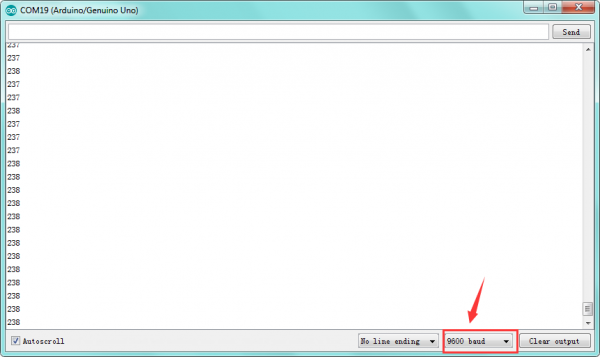
See the light intensity on the serial monitor.
Circuit 5: Buzzer
About this circuit:
In this project, you will learn how to make tones with a buzzer.
What You Need:
- REV4 Baseplate
- Passive Buzzer x 1
- Jumper wires x 2
- USB cable x 1
Component Introduction:
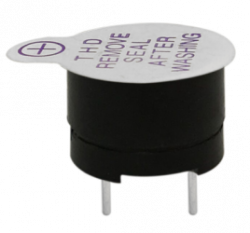
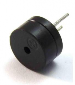
Passive Buzzer:
Buzzers can be categorized as active and passive ones.
The difference between the two is that an active buzzer has a built-in oscillating source, so it will generate a sound when electrified.
A passive buzzer does not have such a source, so DC signal cannot drive it beep. Different frequencies produce different sounds. By the buzzer, you can even play a song.

Hookup Guide:
Wiring the buzzer connected to the REV4 board, the red (positive) to the pin8, black wire (negative) to the GND.
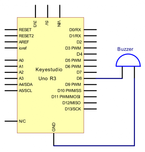
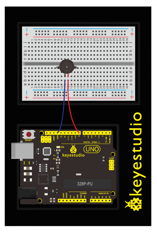
Upload Code:
- 1)Connect the REV4 Board to a USB port on your computer.
- 2)Open the program in the code folder- Circuit 5 Buzzer, or directly copy and paste the code below on the Ardunio IDE.
- 3)Select UPLOAD to program the sketch on the REV4 Board.
After the connection, let's begin the program compiling.
int buzzer=8;// select digital IO pin for the buzzer
void setup()
{
pinMode(buzzer,OUTPUT);// set digital IO pin pattern, OUTPUT to be output
}
void loop()
{ unsigned char i,j;//define variable
while(1)
{ for(i=0;i<80;i++)// output a frequency sound
{ digitalWrite(buzzer,HIGH);// sound
delay(1);//delay1ms
digitalWrite(buzzer,LOW);//not sound
delay(1);//ms delay
}
for(i=0;i<100;i++)// output a frequency sound
{ digitalWrite(buzzer,HIGH);// sound
digitalWrite(buzzer,LOW);//not sound
delay(2);//2ms delay
}
}
}
Test Reult:
Done uploading the code to the board, the passive buzzer will make a tone.
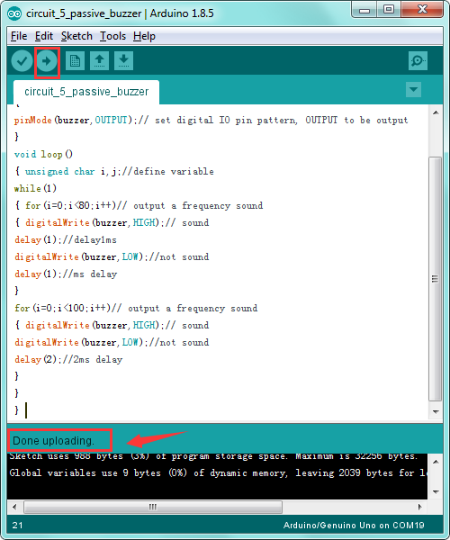
Troubleshooting:
- No sound is playing?
Check your wiring of the buzzer. It’s easy to misalign a pin with a jumper wire or reverse the buzzer.
The use method is almost the same.
Think about it and try to make an audible beep from active buzzer.
Test code is showed below:
int buzzer=2;// initialize digital IO pin that controls the buzzer
void setup()
{
  pinMode(buzzer,OUTPUT);// set pin mode as “output”
}
void loop()
{
digitalWrite(buzzer, HIGH); // produce sound
}
From the test code, we can know the buzzer’s positive lead (long lead) is connected to Digital pin 2 of REV4. The short lead is connected to ground.
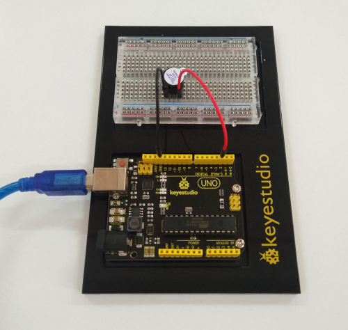
Troubleshooting:
- No sound playing?
Check your wiring of the buzzer. It’s easy to misalign a pin with a jumper wire or reverse the buzzer.
Circuit 6: Button
About this circuit:
Buttons are all around us, from the keys on your keyboard to the buttons on your remote control.
In this circuit, you’ll learn how to use the button to control the LED on and off using digital input.
What You Need:
- REV4 Baseplate
- Button x 1
- Red LED x 1
- 220Ω Resistor x 1
- 10KΩ Resistor x 1
- Jumper wires x 5
- USB cable x 1
Component Introduction:
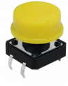
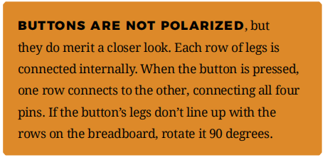
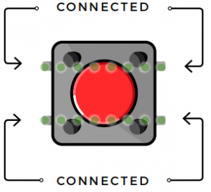
Push Button:
Also known as momentary switches, buttons only remain in their ON state as long as they’re being actuated, or pressed.
Most often momentary switches are best used for intermittent user-input cases: reset button and keypad buttons.
These switches have a nice, tactile, “clicky” feedback when you press them.
Note that the different colors are just aesthetic. All of the buttons included behave the same, no matter their color.
Hookup Guide:
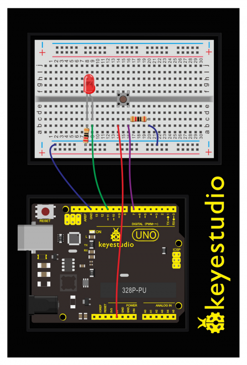
See the wiring diagram below to connect everything.
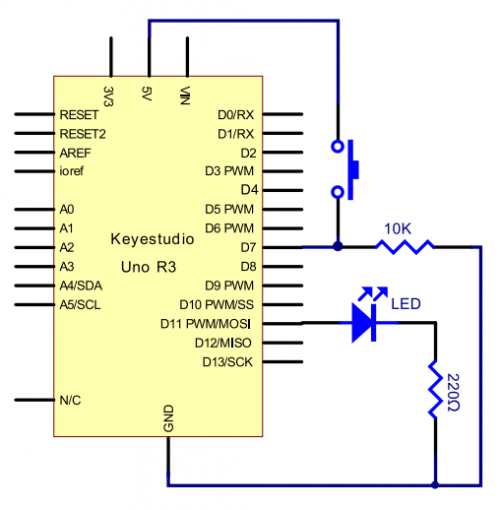
Schematics:
Upload Code:
- 1)Connect the REV4 Board to a USB port on your computer.
- 2)Open the program in the code folder- Circuit 6 Button, or directly copy and paste the code below on the Ardunio IDE.
- 3)Select UPLOAD to program the sketch on the REV4 Board.
Now, let's begin the compiling. When the button is pressed, the LED will be on. After the previous study, the coding should be easy for you. In this program, we add a statement of judgment. Here, we use an if () statement.
Arduino IDE is based on C language, so statements of C language such as while, switch, can certainly be used for Arduino program.
When we press the button, pin 7 will output high level. We can program pin 11 to output high level and turn on the LED. When pin 7 outputs low level, pin 11 also outputs low level and the LED remains off.
int ledpin=11;// initialize pin 11
int inpin=7;// initialize pin 7
int val;// define val
void setup()
{
pinMode(ledpin,OUTPUT);// set LED pin as “output”
pinMode(inpin,INPUT);// set button pin as “input”
}
void loop()
{
val=digitalRead(inpin);// read the level value of pin 7 and assign if to val
if(val==LOW)// check if the button is pressed, if yes, turn on the LED
{ digitalWrite(ledpin,LOW);}
else
{ digitalWrite(ledpin,HIGH);}
}
Code Explanation:
- Single line comments start with // and everything up until the end of that line is considered a comment.
Comments are a great way to leave notes in your code explaining why you wrote it the way you did.
- To declare a standard input, use the line pinMode(pin, INPUT);
digitalRead(pin);
Check to see if an input pin is reading HIGH (5V) or LOW (0V). Returns TRUE (1) or FALSE (0) depending on the reading.
What You Will See:
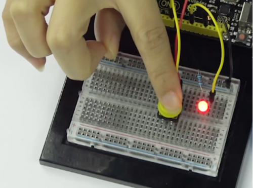
When the button is pressed, LED is on; otherwise, LED remains off.
After the above process, the button controlled LED experiment is completed.
The simple principle of this experiment is widely used in a variety of circuit and electric appliances.
Troubleshooting:
- The buttons are not working
First, make sure that the wiring is correct. It is easy to misalign a wire with a button leg. Second, make sure that you have declared your buttons as inputs.
Think about:
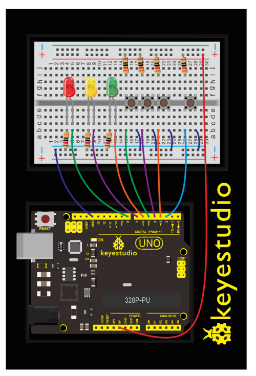
How to make responder effect?
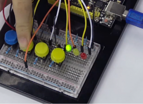
Create your own exciting game. You can try to use three buttons to control three LEDs, one button used as reset button to make a responder. See what will happen?
Upload Code:
int redled=8;     // set red LED as “output”
int yellowled=7;  // set yellow LED as “output”
int greenled=6;   // set green LED as “output”
int redpin=5;     // initialize pin for red button
int yellowpin=4;  // initialize pin for yellow button
int greenpin=3;   // initialize pin for green button
int restpin=2;   // initialize pin for reset button
int red;
int yellow;
int green;
void setup()
{
pinMode(redled,OUTPUT);
pinMode(yellowled,OUTPUT);
pinMode(greenled,OUTPUT);
pinMode(redpin,INPUT);
pinMode(yellowpin,INPUT);
pinMode(greenpin,INPUT);
}
void loop()  // repeatedly read pins for buttons
{
red=digitalRead(redpin);
yellow=digitalRead(yellowpin);
green=digitalRead(greenpin);
if(red==LOW)RED_YES();
if(yellow==LOW)YELLOW_YES();
if(green==LOW)GREEN_YES();
}

void RED_YES()// execute the code until red light is on; end cycle when reset button is pressed
{
  while(digitalRead(restpin)==1)
  {
   digitalWrite(redled,HIGH);
   digitalWrite(greenled,LOW);
   digitalWrite(yellowled,LOW);
  }
  clear_led();
}
void YELLOW_YES()// execute the code until yellow light is on; end cycle when reset button is pressed
{
  while(digitalRead(restpin)==1)
  {
  digitalWrite(redled,LOW);
  digitalWrite(greenled,LOW);
  digitalWrite(yellowled,HIGH);
  }
  clear_led();
}
void GREEN_YES()// execute the code until green light is on; end cycle when reset button is pressed
{
  while(digitalRead(restpin)==1)
  {
  digitalWrite(redled,LOW);
  digitalWrite(greenled,HIGH);
  digitalWrite(yellowled,LOW);
  }
  clear_led();
}
void clear_led()// all LED off
{
  digitalWrite(redled,LOW);
  digitalWrite(greenled,LOW);
  digitalWrite(yellowled,LOW);
}
Press the button to turn corresponding LED on and off.
Circuit 7: 74HC595 And Segment Display
About this circuit:
In this circuit, we will use the 74HC595 shift register to control the segment display. The segment display will show number from 0-9.
What You Need:
- REV4 Baseplate
- 1-digit 7-seg Display x 1
- 74HC595 IC x 1
- 220Ω Resistor x 8
- Jumper wires x 19
- USB cable x 1
Component Introduction:
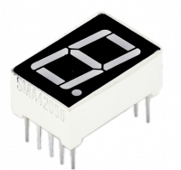
Seven segment display:
LED segment display is a semiconductor light-emitting device. Its basic unit is a light-emitting diode (LED).
For the common anode display, connect the common anode (COM) to +5V. When the cathode level of a certain segment is low, the segment is on; when the cathode level of a certain segment is high, the segment is off.
For the common cathode display, connect the common cathode (COM) to GND. When the anode level of a certain segment is high, the segment is on; when the anode level of a certain segment is low, the segment is off.
Each segment of the display consists of an LED. So when you use it, you also need to use a current-limiting resistor. Otherwise, LED will be burnt out.
When using 1-digit 7-segment display please notice that if it is common anode, the common anode pin connects to the power source; if it is common cathode, the common cathode pin connects to the GND.
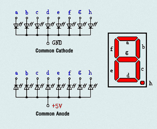
In this experiment, we use a common cathode display.
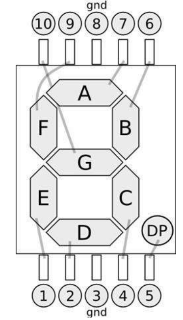
Below is the seven-segment pin diagram.
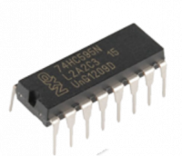
74HC595 IC:
The shift register operates in a fairly simple way, but can be modified to become very complicated but very useful.
We can control the shift of the register with clock pulses.
As we raise the signal going to the clock pin to high, the clock is moved forward one step, and when we pull it low and high again it shifts another.
Each time we shift the clock we switch the input to a different one of the eight registers.
We are essentially controlling the output of each of the eight pins one at a time, and as we move one clock signal forward, we switch to the next output pin to control.
The shift register can be a great tool when you are short on output pins, taking 8 outputs from only about 3 actual data inputs.
It can be added to for some really complicated applications, and they can be daisy-chained together for even more output options.
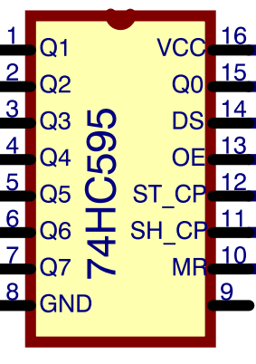
In this project, we only use three I\O ports to control a, b, c, d, e, f, g and dp, therefore control the segment display.
Hookup Guide:
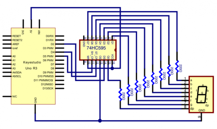
Check out the circuit diagram and hookup table below to see how everything is connected.
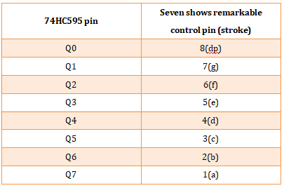
The following table shows the seven-segment display 74HC595 pin correspondence table:
Step one: Connect 74HC595
First, the wiring is connected to power and ground:
- VCC (pin 16) and MR (pin 10) connected to 5V
- GND (pin 8) and OE (pin 13) to ground
Connection DS, ST_CP and SH_CP pin:
- DS (pin 14) connected to REV4 board Digital pin 2;
- ST_CP (pin 12, latch pin) connected to REV4 Digital pin 4;
- SH_CP (pin 11, clock pin) connected to REV4 Digital PWM pin 5.
Step two: Connect the seven segment display
The seven-segment display pin 9 to REV4 board GND
According to the table above, connect the 74HC595 Q0 ~ Q7 to seven-segment display corresponding pin (A ~ G and DP), and then each foot in a 220 ohm resistor in series.
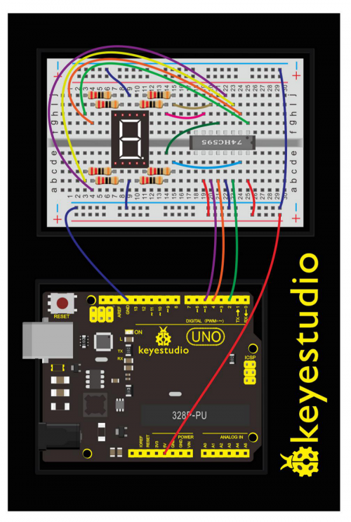
Upload Code:
- 1)Connect the REV4 Board to a USB port on your computer.
- 2)Open the program in the code folder- Circuit 7, or directly copy and paste the code below on the Ardunio IDE.
- 3)Select UPLOAD to program the sketch on the REV4 Board.
int latchPin = 4;
int clockPin = 5;
int dataPin = 2; //define three pins
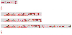
void setup ()
{
  pinMode(latchPin,OUTPUT);
  pinMode(clockPin,OUTPUT);
  pinMode(dataPin,OUTPUT); //three pins as output
}
void loop()
{

  int a[10]={
    252,96,218,242,102,182,190,224,254,246};   //define functional array
  for(int x=0; x<10 ;x++ )                        //calculate counting function
  {
    digitalWrite(latchPin,LOW);
    shiftOut(dataPin,clockPin,MSBFIRST,a[x]);     //display array a[x]
    digitalWrite(latchPin,HIGH);
    delay(1000);
  }
}
Code Explanation:
- Single line comments start with // and everything up until the end of that line is considered a comment.
Comments are a great way to leave notes in your code explaining why you wrote it the way you did.
- The first thing we do is define the three pins we are going to use.
These are the REV4 digital outputs that will be connected to the latch, clock and data pins of the 74HC595.
int latchPin = 4;
int clockPin = 5;
int dataPin = 2; //define three pins
- The 'setup' function just sets the three pins we are using to be digital outputs.
What You Will See:
Hookup well and upload the code to board, you can count the numbers on segment display from 0 to 9.
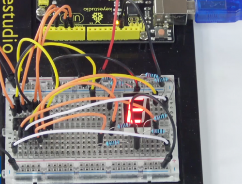
Troubleshooting:
- Upload failed?
Make sure you have assembled the circuit correctly and verified and uploaded the code to your board. Ensure that you are on the correct Board and Serial Port.
- No number showing on 1-digit Segment ?
Check out the wiring between the 1-digit LED display and 74HC595 IC.
Circuit 8: 4-Digit Segment Display
About this circuit:
In this lesson, you will learn how to use a 4-digit 7-segment display. We make the display show changing numbers among 0000-9999.
What You Need:
- REV4 Baseplate
- 4-digit 7-seg Display x 1
- 220Ω Resistor x 8
- Jumper wires x 12
- USB cable x 1
Component Introduction:
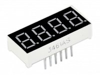
4-Digit Segment Display:
LED segment display is a semiconductor light-emitting device. Its basic unit is a light-emitting diode (LED).
The display features one decimal point per digit. The hardware interface is twelve (two rows of six) through-hole pins, counting from 1 to 12 anticlockwise.
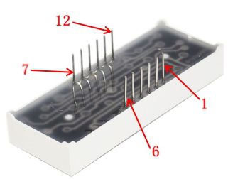
Manual for LED segment display:
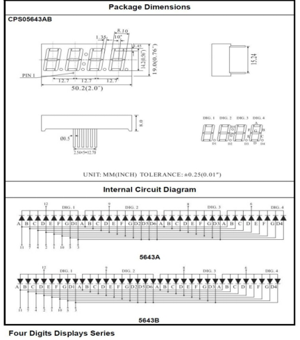
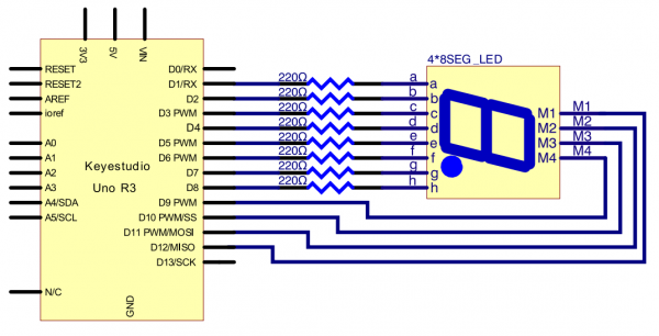
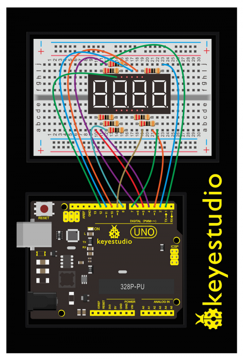
Hookup Guide:
Check out the circuit diagram and hookup table below to see how everything is connected.
Upload Code:
- 1)Connect the REV4 Board to a USB port on your computer.
- 2)Open the program in the code folder- Circuit 8, or directly copy and paste the code below on the Ardunio IDE.
- 3)Select UPLOAD to program the sketch on the REV4 Board.
int a = 1;
int b = 2;
int c = 3;
int d = 4;
int e = 5;
int f = 6;
int g = 7;
int dp = 8;

int d4 = 9;
int d3 = 10;
int d2 = 11;
int d1 = 12;

// set variable
long n = 1230;
int x = 100;
int del = 55;    // fine adjustment for clock

void setup()
{
  pinMode(d1, OUTPUT);
  pinMode(d2, OUTPUT);
  pinMode(d3, OUTPUT);
  pinMode(d4, OUTPUT);
  pinMode(a, OUTPUT);
  pinMode(b, OUTPUT);
  pinMode(c, OUTPUT);
  pinMode(d, OUTPUT);
  pinMode(e, OUTPUT);
  pinMode(f, OUTPUT);
  pinMode(g, OUTPUT);
  pinMode(dp, OUTPUT);
}
/////////////////////////////////////////////////////////////
void loop()
{
  int a=0;
  int b=0;
  int c=0;
  int d=0;
  unsigned long currentMillis = millis();

  while(d>=0)
  {
    while(millis()-currentMillis<10)
     {
      Display(1,a);
      Display(2,b);
      Display(3,c);
      Display(4,d);
     }
    currentMillis = millis();
    d++;
  if (d>9)
  {
   c++;
   d=0;
  }
    if (c>9)
  {
   b++;
   c=0;
  }
    if (b>9)
  {
   a++;
   b=0;
  }
    if (a>9)
  {
   a=0;
   b=0;
   c=0;
   d=0;
  }
  }
}
///////////////////////////////////////////////////////////////
void WeiXuan(unsigned char n)//
{
  switch (n)
  {
    case 1:
      digitalWrite(d1, LOW);
      digitalWrite(d2, HIGH);
      digitalWrite(d3, HIGH);
      digitalWrite(d4, HIGH);
      break;
    case 2:
      digitalWrite(d1, HIGH);
      digitalWrite(d2, LOW);
      digitalWrite(d3, HIGH);
      digitalWrite(d4, HIGH);
      break;
    case 3:
      digitalWrite(d1, HIGH);
      digitalWrite(d2, HIGH);
      digitalWrite(d3, LOW);
      digitalWrite(d4, HIGH);
      break;
    case 4:
      digitalWrite(d1, HIGH);
      digitalWrite(d2, HIGH);
      digitalWrite(d3, HIGH);
      digitalWrite(d4, LOW);
      break;
    default :
      digitalWrite(d1, HIGH);
      digitalWrite(d2, HIGH);
      digitalWrite(d3, HIGH);
      digitalWrite(d4, HIGH);
      break;
  }
}
void Num_0()
{
  digitalWrite(a, HIGH);
  digitalWrite(b, HIGH);
  digitalWrite(c, HIGH);
  digitalWrite(d, HIGH);
  digitalWrite(e, HIGH);
  digitalWrite(f, HIGH);
  digitalWrite(g, LOW);
  digitalWrite(dp, LOW);
}
void Num_1()
{
  digitalWrite(a, LOW);
  digitalWrite(b, HIGH);
  digitalWrite(c, HIGH);
  digitalWrite(d, LOW);
  digitalWrite(e, LOW);
  digitalWrite(f, LOW);
  digitalWrite(g, LOW);
  digitalWrite(dp, LOW);
}
void Num_2()
{
  digitalWrite(a, HIGH);
  digitalWrite(b, HIGH);
  digitalWrite(c, LOW);
  digitalWrite(d, HIGH);
  digitalWrite(e, HIGH);
  digitalWrite(f, LOW);
  digitalWrite(g, HIGH);
  digitalWrite(dp, LOW);
}
void Num_3()
{
  digitalWrite(a, HIGH);
  digitalWrite(b, HIGH);
  digitalWrite(c, HIGH);
  digitalWrite(d, HIGH);
  digitalWrite(e, LOW);
  digitalWrite(f, LOW);
  digitalWrite(g, HIGH);
  digitalWrite(dp, LOW);
}
void Num_4()
{
  digitalWrite(a, LOW);
  digitalWrite(b, HIGH);
  digitalWrite(c, HIGH);
  digitalWrite(d, LOW);
  digitalWrite(e, LOW);
  digitalWrite(f, HIGH);
  digitalWrite(g, HIGH);
  digitalWrite(dp, LOW);
}
void Num_5()
{
  digitalWrite(a, HIGH);
  digitalWrite(b, LOW);
  digitalWrite(c, HIGH);
  digitalWrite(d, HIGH);
  digitalWrite(e, LOW);
  digitalWrite(f, HIGH);
  digitalWrite(g, HIGH);
  digitalWrite(dp, LOW);
}
void Num_6()
{
  digitalWrite(a, HIGH);
  digitalWrite(b, LOW);
  digitalWrite(c, HIGH);
  digitalWrite(d, HIGH);
  digitalWrite(e, HIGH);
  digitalWrite(f, HIGH);
  digitalWrite(g, HIGH);
  digitalWrite(dp, LOW);
}
void Num_7()
{
  digitalWrite(a, HIGH);
  digitalWrite(b, HIGH);
  digitalWrite(c, HIGH);
  digitalWrite(d, LOW);
  digitalWrite(e, LOW);
  digitalWrite(f, LOW);
  digitalWrite(g, LOW);
  digitalWrite(dp, LOW);
}
void Num_8()
{
  digitalWrite(a, HIGH);
  digitalWrite(b, HIGH);
  digitalWrite(c, HIGH);
  digitalWrite(d, HIGH);
  digitalWrite(e, HIGH);
  digitalWrite(f, HIGH);
  digitalWrite(g, HIGH);
  digitalWrite(dp, LOW);
}
void Num_9()
{
  digitalWrite(a, HIGH);
  digitalWrite(b, HIGH);
  digitalWrite(c, HIGH);
  digitalWrite(d, HIGH);
  digitalWrite(e, LOW);
  digitalWrite(f, HIGH);
  digitalWrite(g, HIGH);
  digitalWrite(dp, LOW);
}
void Clear()    // clear the screen
{
  digitalWrite(a, LOW);
  digitalWrite(b, LOW);
  digitalWrite(c, LOW);
  digitalWrite(d, LOW);
  digitalWrite(e, LOW);
  digitalWrite(f, LOW);
  digitalWrite(g, LOW);
  digitalWrite(dp, LOW);
}
void pickNumber(unsigned char n)// select number
{
  switch (n)
  {
    case 0: Num_0();

      break;
    case 1: Num_1();
      break;
    case 2: Num_2();
      break;
    case 3: Num_3();
      break;
    case 4: Num_4();
      break;
    case 5: Num_5();
      break;
    case 6: Num_6();
      break;
    case 7: Num_7();
      break;
    case 8: Num_8();
      break;
    case 9: Num_9();
      break;
    default: Clear();
      break;
  }
}
void Display(unsigned char x, unsigned char Number)//    take x as coordinate and display number
{
  WeiXuan(x);
  pickNumber(Number);
  delay(1);
  Clear() ; // clear the screen
}
What You Will See:
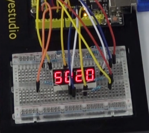
Hookup well and upload the code to board, the 4-digit LED display will show the jumping number among 0000-9999.
Troubleshooting:
- No number jumping on 4-digit Segment ?
Check out the wiring between the 1-digit LED display and UNO.
Circuit 9: LED Matrix Display
About this circuit:
In this circuit, you will learn how to control the LED matrix showing the number.
What You Need:
- REV4 Baseplate
- LED matrix display x 1
- 220Ω Resistor x 8
- Jumper wires x 16
- USB cable x 1
Component Introduction:
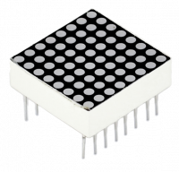
LED Matrix display:
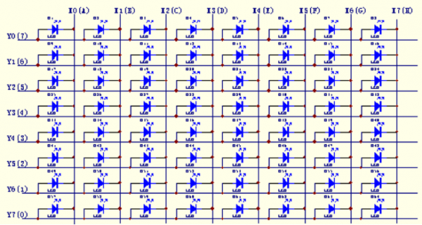
Now, we are going to learn 8*8 dot matrix. It consists of 64 LEDs, located in every crossing of each row and column.
Welding pins on the 8*8 dot matrix:
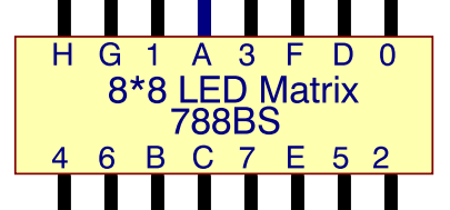
When a row is at level 1, and a column at level 0 simultaneously, LED lights up that is between high and low level.
For instance, if you want to light up the first LED, connect pin 7 to high level, and pin A to low level; if you want to light up LEDs in first row, connect pin 7 to high level, and pin A, B, C, D, E, F, G, H to low level; if you want to light up LEDs in first column, connect pin A to high level, and pin 0, 1, 2, 3, 4, 5, 6, 7 to low level shown as below figure.
Hookup Guide:
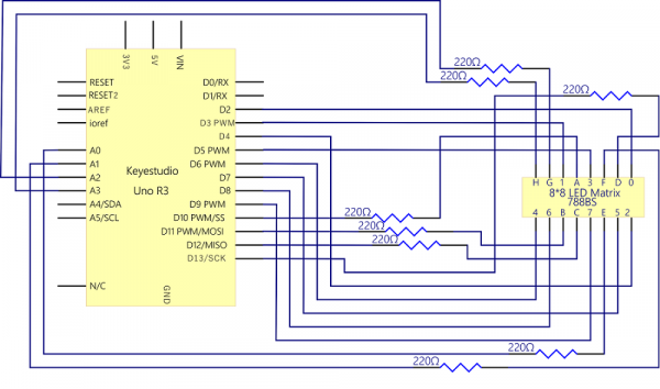
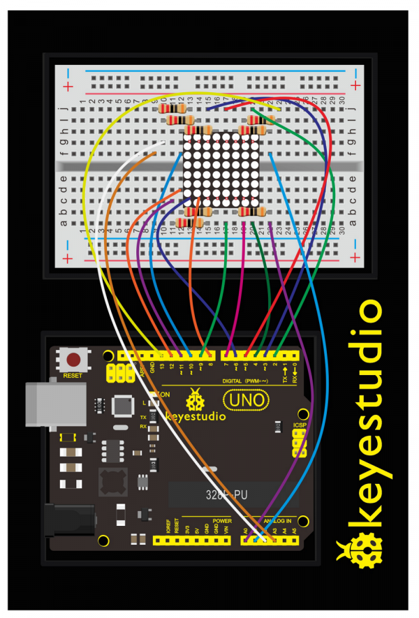
Check out the circuit diagram and hookup table below to see how everything is connected.
Upload Code:
- 1)Connect the REV4 Board to a USB port on your computer.
- 2)Open the program in the code folder- Circuit 9, or directly copy and paste the code below on the Ardunio IDE.
- 3)Select UPLOAD to program the sketch on the REV4 Board.
//define an array to store “0”
unsigned char Text[]={0x00,0x1c,0x22,0x22,0x22,0x22,0x22,0x1c};
void Draw_point(unsigned char x,unsigned char y)//draw-point function
{
   clear_();
   digitalWrite(x+2, HIGH);
   digitalWrite(y+10, LOW);
   delay(1);
}
void show_num(void)//show function and invoke draw-point function
{
  unsigned char i,j,data;
  for(i=0;i<8;i++)
  {
    data=Text[i];
    for(j=0;j<8;j++)
    {
      if(data & 0x01)Draw_point(j,i);
      data>>=1;
    }
  }
}
void setup(){
int i = 0 ;
for(i=2;i<18;i++)
 {
   pinMode(i, OUTPUT);
  }
  clear_();
}
void loop()
{
  show_num();
}
void clear_(void)//clear screen
{
  for(int i=2;i<10;i++)
  digitalWrite(i, LOW);
  for(int i=0;i<8;i++)
  digitalWrite(i+10, HIGH);
}
What You Will See:
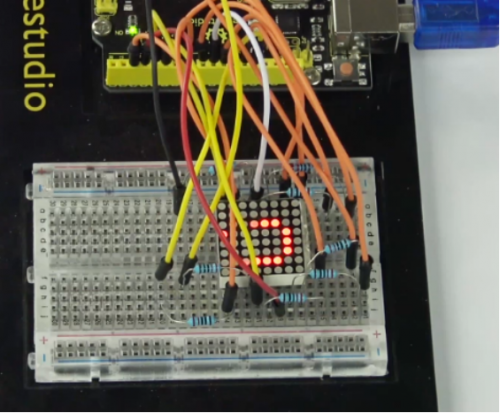
Hookup well and upload the code to board, the LED matrix is displaying the “0”.
Troubleshooting:
- No number displaying on 8*8 LED matrix ?
Check out the wiring between the 8*8 LED matrix display and UNO.
Circuit 10: LCD “Hello, World!”
About this circuit:
Printing “Hello, world!” is usually the first thing that programming tutorials will have you do in a new language.
Now we’re going to print out real text using a Liquid Crystal Display (LCD).
What You Need:
- REV4 Baseplate
- 1602 LCD display x 1
- Jumper wires x 4
- USB cable x 1
Component Introduction:
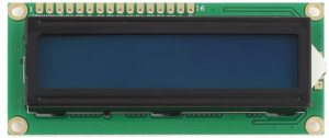
1602 LCD display:
Designed to show a grid of letters, numbers and other special characters, LCDs are great for printing data and showing values.
Adding an LCD to your project will make it super portable and allow you to integrate up to 32 characters (16x2) of information.
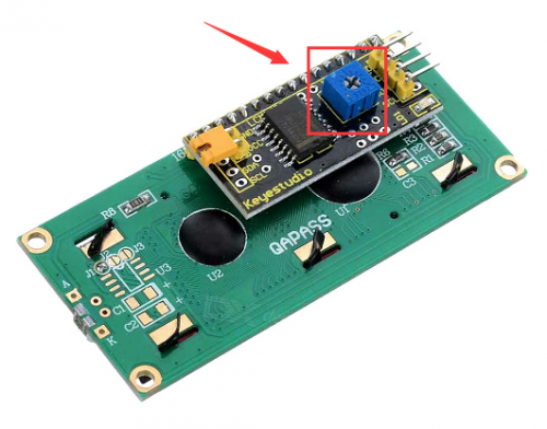
On the back of LCD display there is a blue potentiometer. You can turn the potentiometer to adjust the contrast. Notice that the screen will get brighter or darker and that the characters become more visible or less visible.
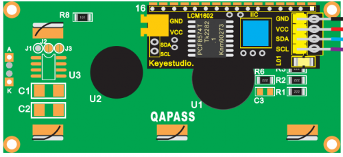
Introduction to the pins of LCD1602:
- GND: A pin that connects to ground
- VCC: A pin that connects to a +5V power supply
- SDA: A pin that connects to analog port A4 for IIC communication
- SCL: A pin that connects to analog port A5 for IIC communication
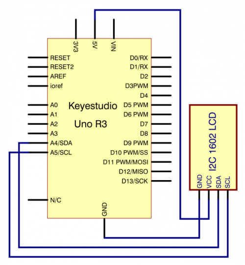
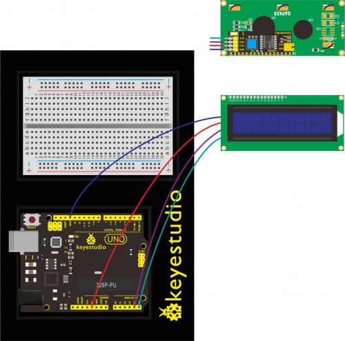
Hookup Guide:
Check out the circuit diagram and hookup table below to see how everything is connected.
Upload Code:
- 1)Note: Before you can run this, make sure that you have installed the < LiquidCrystal > library or re-install it, if necessary. Otherwise, your code won't work.
- 2)Connect the REV4 Board to a USB port on your computer.
- 3)Open the program in the code folder- Circuit 10, or directly copy and paste the code below on the Ardunio IDE.
- 4)Select UPLOAD to program the sketch on the REV4 Board.
#include <Wire.h>
#include <LiquidCrystal_I2C.h>
LiquidCrystal_I2C lcd(0x27,16,2); // set the LCD address to 0x27 for a 16 chars and 2 line display
void setup()
{
lcd.init(); // initialize the lcd
lcd.init();
// Print a message to the LCD.
lcd.backlight();
lcd.setCursor(3,0);
lcd.print("Hello, world!");
lcd.setCursor(2,1);
lcd.print("keyestudio!");
}
void loop()
{
}
Code Explanation:
- Single line comments start with // and everything up until the end of that line is considered a comment.
Comments are a great way to leave notes in your code explaining why you wrote it the way you did.
- The first thing of note in the sketch is the line:
#include <LiquidCrystal.h>
This tells Arduino that we wish to use the Liquid Crystal library.
- After uploading this code, make sure the backlight is lit up, and adjust the potentiometer all the way around until you see the text message
- In the 'setup' function, we have two commands:
lcd.setCursor(3,0);
lcd.print("Hello, world!");
The first sets the cursor position (where the next text will appear) to column 3 & row 0.
The second line displays the message that we see on the first line of the screen.
What You Will See:
Hookup well and upload the code to board, you should see the words “ Hello, World!” and “keyestudio” pop up on your LCD.
Remember you can adjust the contrast using the potentiometer if you can’t make out the words clearly.
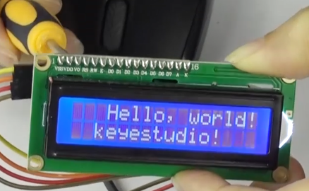
If you have any issues, make sure your code is correct and double-check your connections.
Troubleshooting:
- LCD Display Not Clear?
Remember you can adjust the contrast using the potentiometer if you can’t make out the words clearly.
Circuit 11: Temperature Sensor
About this circuit:
In this circuit you can use a small, low-cost sensor like the LM35 to make devices that track and respond to temperature.
What You Need:
- REV4 Baseplate
- Red LED x 1
- Yellow LED x 1
- Green LED x 1
- LM35 temperature sensor x 1
- 220Ω Resistor x 3
- Jumper wires x 7
- USB cable x 1
Component Introduction:
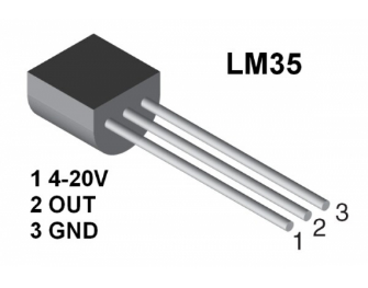
LM35 temperature sensor:
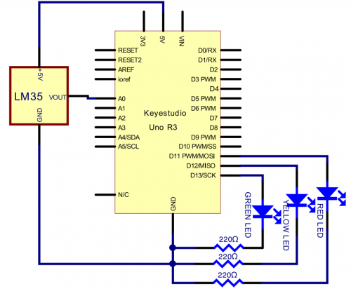
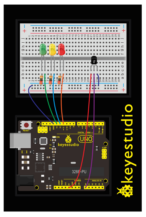
This temperature sensor has three legs. One connects to 5V, one to ground, and the voltage output from the second leg varies proportionally to changes in temperature.
Hookup Guide:
See how everything is connected in the below figures.
Upload Code:
- 1)Connect the REV4 Board to a USB port on your computer.
- 2)Open the program in the code folder- Circuit 11, or directly copy and paste the code below on the Ardunio IDE.
- 3)Select UPLOAD to program the sketch on the REV4 Board.
void setup() {
Serial.begin(9600);
  pinMode(13, OUTPUT);
  pinMode(12, OUTPUT);
  pinMode(11, OUTPUT);
}
void loop() {
  int vol = analogRead(A0) * (5.0 / 1023.0*100);   // read temperature value of LM35
Serial.print("Tep:");
 Serial.print(vol);
 Serial.println("C");
if (vol<28)                     // low temperature area and LED setup
{
  digitalWrite(13, HIGH);
  digitalWrite(12, LOW);
  digitalWrite(11, LOW);
}
else if (vol>=28 && vol<=30)
 {
   digitalWrite(13, LOW);

  digitalWrite(12, HIGH);
  digitalWrite(11, LOW);
}
else if (vol>30)                               //  low temperature area and LED setup

{
   digitalWrite(13, LOW);
  digitalWrite(12, LOW);
  digitalWrite(11, HIGH);
}
 }
What You Will See:
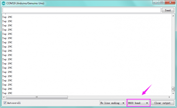
After uploading the code, open the serial monitor, it will show the temperature value.
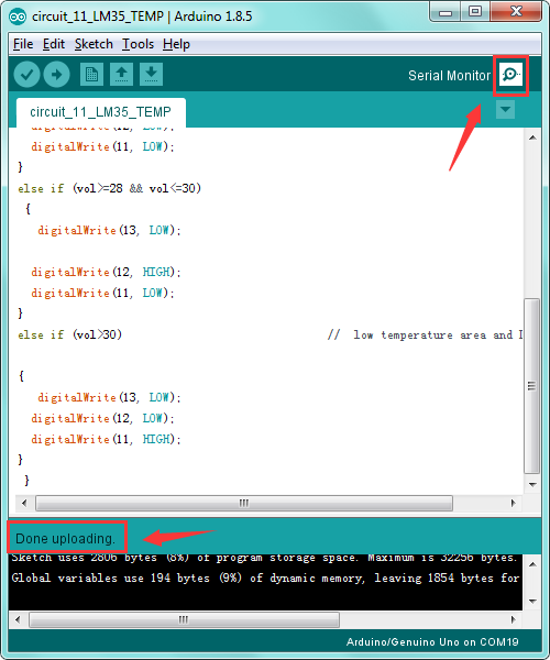
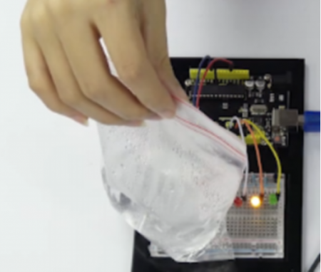
Corresponding LED will be turned on in accordance with corresponding temperature range. Put a bag filled with hot water close to the sensor.
When the temperature is lower than 28℃, green LED turns on;
When it is greater than or equal to 28℃ but less than 30℃, yellow LED turns on; if greater than 30℃, red LED turns on.
Circuit 12: Temperature and Humidity
About this circuit:
In this circuit you will learn how to use a DHT11 Temperature and Humidity Sensor.
It’s accurate enough for most projects that need to keep track of humidity and temperature reading.
What You Need:
- REV4 Baseplate
- DHT11 sensor x 1
- 10KΩ Resistor x 1
- Jumper wires x 5
- USB cable x 1
Component Introduction:
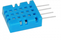
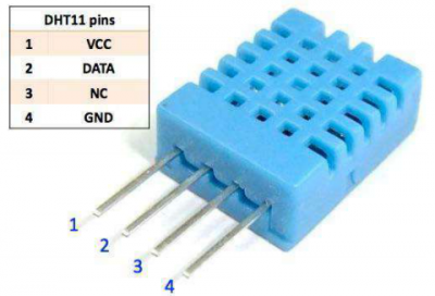
DHT11 Temperature and Humidity Sensor:
This DHT11 Temperature and Humidity Sensor features calibrated digital signal output with the temperature and humidity sensor complex. Its technology ensures high reliability and excellent long-term stability. A high-performance 8-bit microcontroller is connected.
This sensor includes a resistive element and a sense of wet NTC temperature measuring devices. It has excellent quality, fast response, anti-interference ability and high cost performance advantages.
Each DHT11 sensor features extremely accurate calibration data of humidity calibration chamber. The calibration coefficients stored in the OTP program memory, internal sensors detect signals in the process, and we should call these calibration coefficients.
Qualities of small size, low power, and 20-meter signal transmission distance make it a wide applied application and even the most demanding one. Convenient connection, special packages can be provided according to users need.
Hookup Guide:
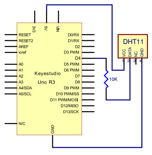
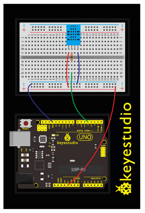
Check out the circuit diagram and hookup table below to see how everything is connected.
Upload Code:
- 1) Note: Before you can run this, make sure that you have installed the < dht11> library or re-install it, if necessary. Otherwise, your code won't work.
- 2)Connect the REV4 Board to a USB port on your computer.
- 3)Open the program in the code folder- Circuit 12, or directly copy and paste the code below on the Ardunio IDE.
- 4)Select UPLOAD to program the sketch on the REV4 Board.
#include <dht11.h>
dht11 DHT;
#define DHT11_PIN 4

void setup(){
Serial.begin(9600);
Serial.println("DHT TEST PROGRAM ");
Serial.print("LIBRARY VERSION: ");
Serial.println(DHT11LIB_VERSION);
Serial.println();
Serial.println("Type,\tstatus,\tHumidity (%),\tTemperature (C)");
}

void loop(){
int chk;
Serial.print("DHT11, \t");
chk = DHT.read(DHT11_PIN);// READ DATA
switch (chk){
case DHTLIB_OK:
Serial.print("OK,\t");
break;
case DHTLIB_ERROR_CHECKSUM:
Serial.print("Checksum error,\t");
break;
case DHTLIB_ERROR_TIMEOUT:
Serial.print("Time out error,\t");
break;
default:
Serial.print("Unknown error,\t");
break;
}
// DISPLAT DATA
Serial.print(DHT.humidity,1);
Serial.print(",\t");
Serial.println(DHT.temperature,1);
delay(1000);
}
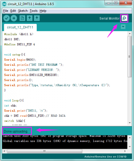
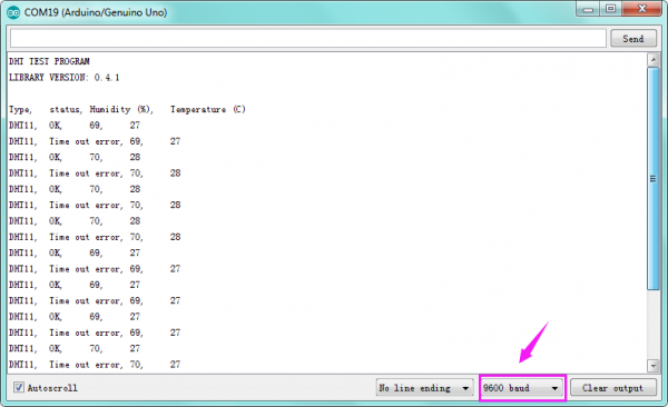
After uploading the code, open the serial monitor, it will show the temperature and humidity value of current environment.
Troubleshooting:
- No Data Display?
Double-check that you have plugged the DTH11 sensor in correctly. Make sure the wiring is no wrong.
Note that here use a 10KΩ Resistor.
Circuit 13: Flame Sensor
About this circuit:
In this circuit you will learn how to use a flame sensor to trigger a buzzer making an alarm when detecting the fire.
What You Need:
- REV4 Baseplate
- Flame sensor x 1
- Active buzzer x 1
- 10KΩ Resistor x 1
- Jumper wires x 6
- USB cable x 1
Component Introduction:
Flame Sensor:
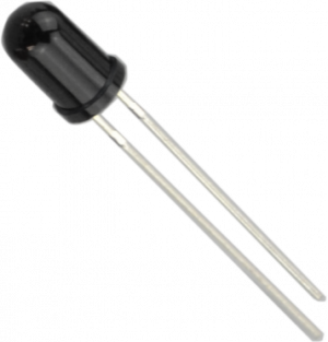
Flame sensor (Infrared receiving triode) is specially used on robots to find the fire source. This sensor is of high sensitivity to flame. Below is a photo of it.
Working Principle:
Flame sensor is made based on the principle that infrared ray is highly sensitive to flame. It has an infrared receiving tube specially designed to detect fire, and then convert the flame brightness to fluctuating level signal. The signals are then input into the central processor and be dealt with accordingly.
Sensor Connection
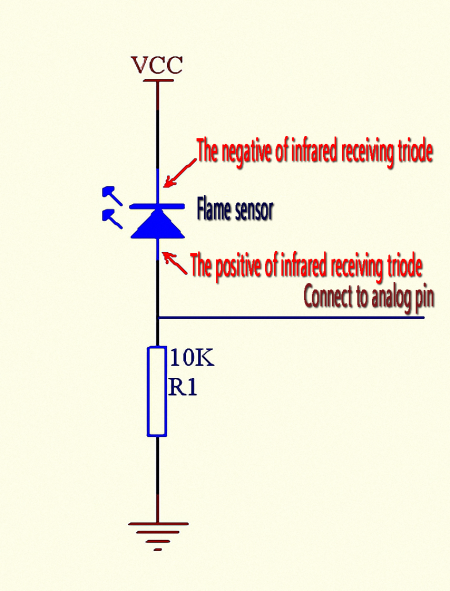
The shorter lead of the receiving triode is for negative, the other one for positive. Connect negative to 5V pin, positive to resistor; connect the other end of the resistor to GND, connect one end of a jumper wire to a clip which is electrically connected to sensor positive, the other end to analog pin. As shown below:
Hookup Guide:
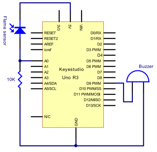
Check out the circuit diagram and hookup table below to see how everything is connected.
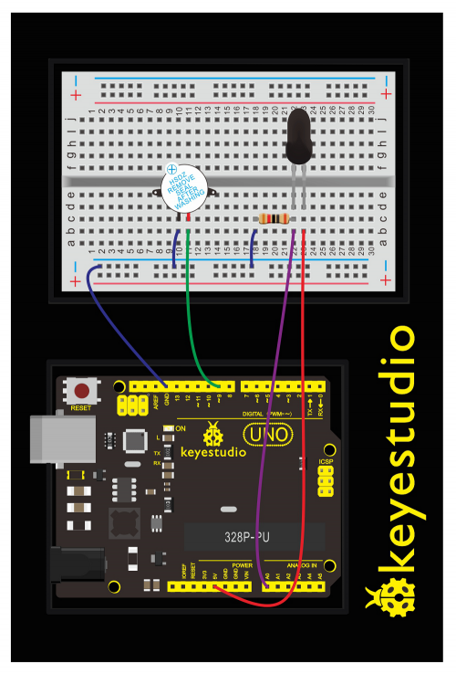
Upload Code:
- 1)Connect the REV4 Board to a USB port on your computer.
- 2)Open the program in the code folder- Circuit 13, or directly copy and paste the code below on the Ardunio IDE.
- 3)Select UPLOAD to program the sketch on the REV4 Board.
When it's approaching a fire, the voltage value read from the analog port differs. If you use a multimeter, you can know when there is no fire approaching, the voltage it reads is around 0.3V; when there is fire approaching, the voltage it reads is around 1.0V.
The nearer the fire, the higher the voltage.
So in the beginning of the program, you can initialize voltage value i (no fire value); Then, continuously read the analog voltage value j and obtain difference value k=j-i; compare k with 0.6V (123 in binary) to determine whether or not there is a fire approaching; if yes, the buzzer will buzz.
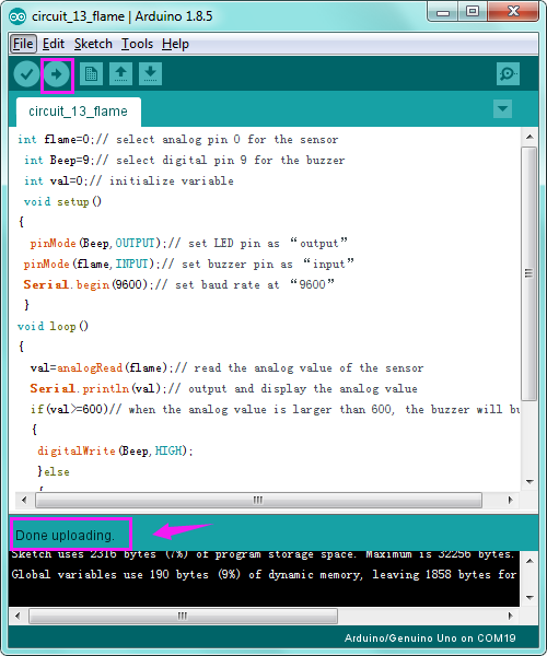
int flame=0;// select analog pin 0 for the sensor
 int Beep=9;// select digital pin 9 for the buzzer
 int val=0;// initialize variable
 void setup()
{
  pinMode(Beep,OUTPUT);// set LED pin as “output”
 pinMode(flame,INPUT);// set buzzer pin as “input”
 Serial.begin(9600);// set baud rate at “9600”
 }
void loop()
{
  val=analogRead(flame);// read the analog value of the sensor
  Serial.println(val);// output and display the analog value
  if(val>=600)// when the analog value is larger than 600, the buzzer will buzz
  {
   digitalWrite(Beep,HIGH);
   }else
   {
     digitalWrite(Beep,LOW);
    }
   delay(500);
}
After uploading the code, once the sensor detects the flame, the buzzer will immediately make a sound. If no fire, everything is normal.
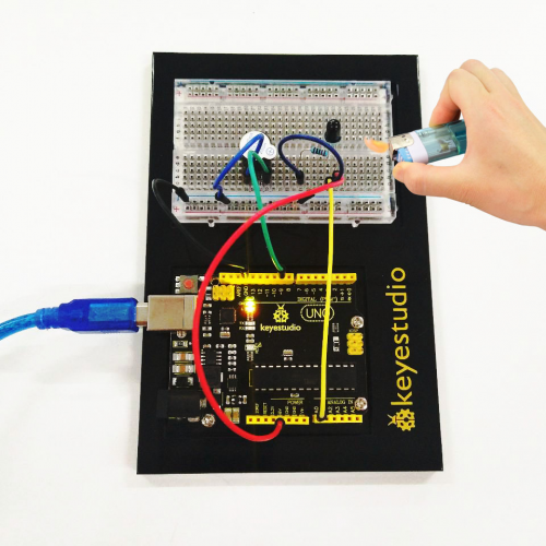
Troubleshooting:
- Buzzer Not Sound?
Double-check that you have plugged them in correctly. The longer lead of the buzzer is positive end. So does the flame sensor.
Note that here use a 10KΩ Resistor.
Circuit 14: Tilt Ball Switch
About this circuit:
In this circuit you will learn how to use two tilt ball switches to control two LED lights on and off.
What You Need:
- REV4 Baseplate
- Tilt ball switch x 2
- Red LED x 1
- 220Ω Resistor x 2
- 10KΩ Resistor x 2
- Jumper wires x 10
- USB cable x 1
Component Introduction:
Tilt ball switch:
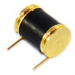
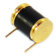
Tilt sensors (tilt ball switch) allow you to detect orientation or inclination. They are small, inexpensive, low-power and easy-to-use. If used properly, they will not wear out.
The tilt-switch twig is the equivalent of a button, and is used as a digital input. Inside the tilt switch is a ball that make contact with the pins when the case is upright. Tilt the case over and the balls don't touch, thus not making a connection. When the switch is level it is open, and when tilted, the switch closes.
It can be used for orientation detection, alarm device or others.
Here is the principle of tilt sensor to illustrate how it works:
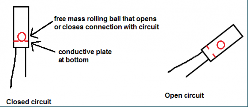
Hookup Guide:
Check out the circuit diagram and hookup table below to see how everything is connected.
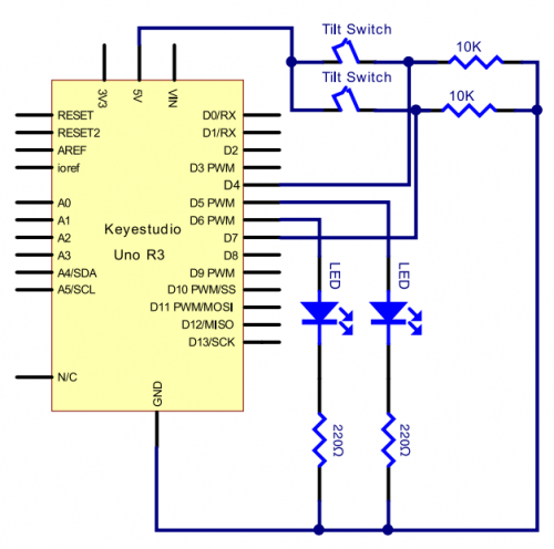
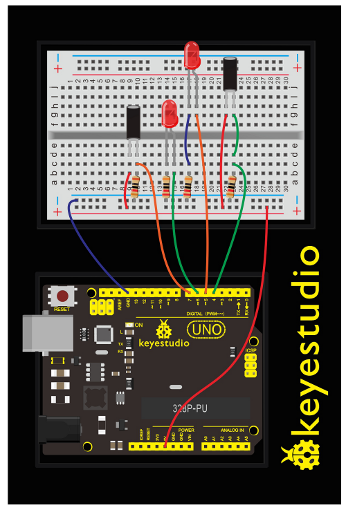
Upload Code:
- 1)Connect the REV4 Board to a USB port on your computer.
- 2)Open the program in the code folder- Circuit 14, or directly copy and paste the code below on the Ardunio IDE.
- 3)Select UPLOAD to program the sketch on the REV4 Board.
int LedPinA = 5;
int LedPinB = 6;
int ButtonPinA = 7;
int ButtonPinB = 4;
int buttonStateA = 0;
int buttonStateB = 0;
int brightnessA = 0;
int brightnessB= 255;
void setup()
{
Serial.begin(9600);
pinMode(LedPinA, OUTPUT);
pinMode(LedPinB, OUTPUT);
pinMode(ButtonPinA, INPUT);
pinMode(ButtonPinB, INPUT);
}
void loop()
{
buttonStateA = digitalRead(ButtonPinA);
if (buttonStateA == HIGH && brightnessA != 255)
{
brightnessA ++;
}
if (buttonStateA == LOW && brightnessA != 0)
{
brightnessA --;
}
analogWrite(LedPinB, brightnessA);
Serial.print(brightnessA);
Serial.print("   ");
buttonStateB = digitalRead(ButtonPinB);
if (buttonStateB == HIGH && brightnessB != 0)
{
brightnessB --;
}
if (buttonStateB == LOW && brightnessB != 255)
{
brightnessB++;
}
analogWrite(LedPinA, brightnessB);
Serial.println(brightnessB);
delay(5);
}
What You Will See:
Tilt the circuit to one side, one LED gradually turns on and another LED turns off.
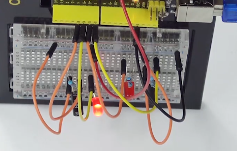
Troubleshooting:
- LED Not Lighting?
Double-check that you have plugged them in correctly. Make sure the connection no wrong.
Circuit 15: Vibration Switch
About this circuit:
In this circuit you will learn how to test the vibration switch.
What You Need:
- REV4 Baseplate
- Vibration switch x 1
- 10KΩ Resistor x 1
- Jumper wires x 3
- USB cable x 1
Component Introduction:
Vibration switch:
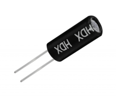
It is a electronic switch that can sense the intensity of vibration and transfer the result to the circuit device, and activate the circuit to start working.
Hookup Guide:
Check out the circuit diagram and hookup table below to see how everything is connected.
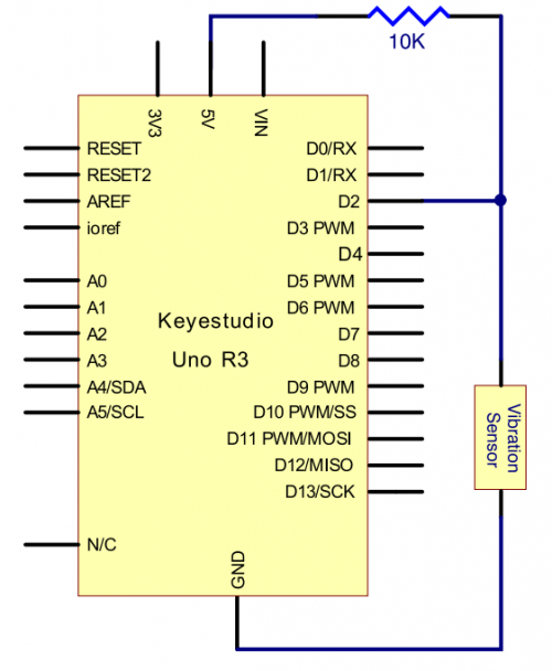
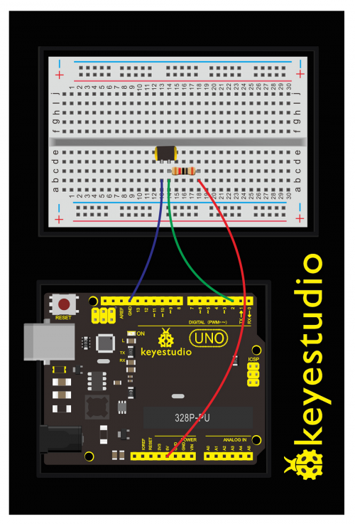
Upload Code:
- 1)Connect the REV4 Board to a USB port on your computer.
- 2)Open the program in the code folder- Circuit 15, or directly copy and paste the code below on the Ardunio IDE.
- 3)Select UPLOAD to program the sketch on the REV4 Board.
#define SensorLED     13
#define SensorINPUT   2
unsigned char state = 0;
void setup()
{
  pinMode(SensorLED, OUTPUT);
  pinMode(SensorINPUT, INPUT);
attachInterrupt(0, blink, FALLING);//D2 as external interruption 0, when there is falling trigger and call blink function

}
void loop()
{
      if(state!=0)
      {
        digitalWrite(SensorLED,HIGH);
        delay(3000);
        state = 0;
      }
      else
        digitalWrite(SensorLED,LOW);
}

void blink()// digital input of the sensor falling, triggering interruption function
{
  state++;
}
What You Will See:
Done uploading the code, vibrate the desk where the sensor placed; once the sensor detects vibration, the D13 led on the REV4 board turns on for 3 seconds then off.
Circuit 16: Sound Sensor
About this circuit:
In this circuit you will learn how to use a microphone sound sensor to turn an LED on and off.
What You Need:
- REV4 Baseplate
- Sound sensor x 1
- Red LED x 1
- 220Ω Resistor x 2
- Jumper wires x 10
- USB cable x 1
Component Introduction:
Sound sensor:
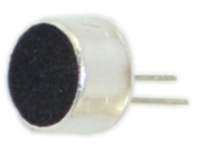
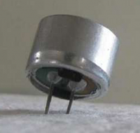
Transducers are devices which convert energy from one form to other. A microphone is a transducer which converts sound energy to electrical signals. It works opposite to a speaker.
These microphones are widely used in electronic circuits to detect minor sounds or air vibrations which in turn are converted to electrical signals for further use. The two legs as shown in the image above are used to make electrical connection with the circuit.
The top face is covered with a porous material with the help of glue. It acts as a filter for the dust particles.
The sound signals/air vibrations passes through the porous material and falls on the diaphragm through the hole shown in the image above.
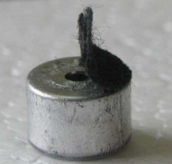
Hookup Guide:
Check out the circuit diagram and hookup table below to see how everything is connected.
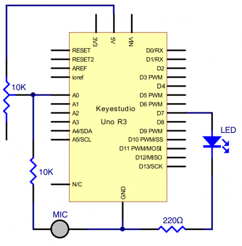
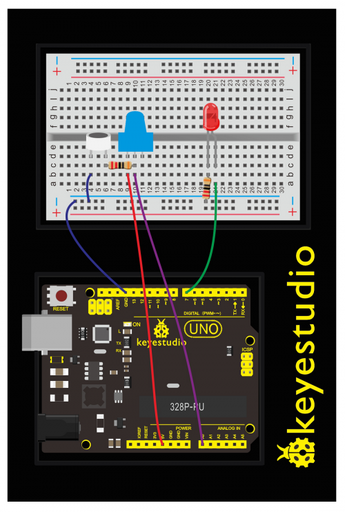
Upload Code:
- 1)Connect the REV4 Board to a USB port on your computer.
- 2)Open the program in the code folder- Circuit 16, or directly copy and paste the code below on the Ardunio IDE.
- 3)Select UPLOAD to program the sketch on the REV4 Board.
int LEDpin = 7;                 // set pin for LED
void setup() {
  Serial.begin(9600);
  pinMode(LEDpin,OUTPUT);
}
void loop() {

  int Soundvalue = analogRead(A0);  // read the input analog value
  Serial.println(Soundvalue);
  if(Soundvalue>700)
  {
   digitalWrite(LEDpin,HIGH);      // when the analog value is bigger than the set value, turn on the LED
   for(int i=0;i<5;i++){
   delay(1000);                    // wait for 5s
   }
  }
  else{
   digitalWrite(LEDpin,LOW);      // turn off the LED
    }
}
Note: It has no processing of the signal from the MIC, so signal is weak and insensitive. Instead of sound signal, we blow air to the MIC.
By rotating the potentiometer, the analog value of A0 changes; After adjusting the potentiometer, blow air into the MIC, and observe the data in the serial monitor.
For example, the displayed data is less than 300 before blowing; after blowing, data is more than 700.
Setup code if (Soundvalue >700), control the LED on and off; the on time of the LED is controlled by the code for(int i=0;i<5;i++) { delay(1000); }, so the light is on for 5*1s.
What You Will See:
Turn the potentiometer to adjust the sensitivity of led light.
Done uploading the code, open the serial monitor and set the baud rate to 9600.
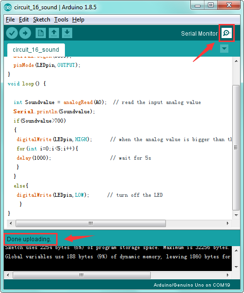
Clapping your hands, you should see the LED turn on for 5 seconds then off. The data is showed on the monitor.
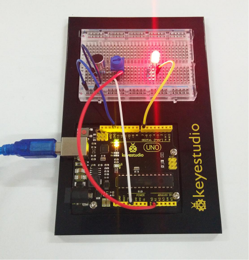
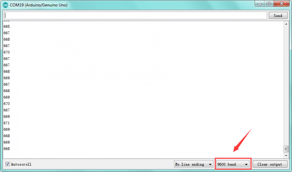
Troubleshooting:
- LED Not Lighting?
Double-check that you have plugged them in correctly. The longer lead is the positive end.
Make sure the sound sensor and potentiometer are assembled correctly.
Circuit 17: Distance Sensor
About this circuit:
Distance sensors are amazing tools with all kinds of uses. They can sense the presence of an object, they can be used in experiments to calculate speed and acceleration, and they can be used in robotics to avoid obstacles.
This circuit will walk you through the basics of using an ultrasonic distance sensor, which measures distance using sound waves!
What You Need:
- REV4 Baseplate
- ultrasonic sensor x 1
- 1602 LCD display x 1
- Jumper wires x 10
- USB cable x 1
Component Introduction:
Ultrasonic sensor:
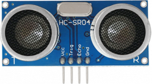
Ultrasonic sensor module HC-SR04 provides 2cm-400cm non-contact measurement function, the ranging accuracy can reach to 3mm.
The modules includes ultrasonic transmitters, receiver and control circuit.
Distance sensors work by sending pulses of light or sound out from a transmitter, then timing how long it takes for the signals to bounce off an object and return to a receiver (just like sonar).
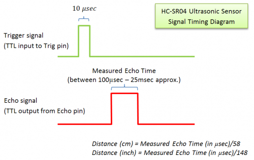
TECH SPECS:
- Operating Voltage: 5V(DC)
- Operating Current: 15mA
- Operating Frequency: 40khz
- Maximum Detection Distance: 3-5m
- Minimum Detection Distance: 3-4cm
- Sensing Angle: less than 15 degrees
Hookup Guide:
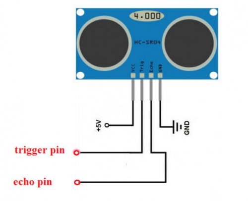
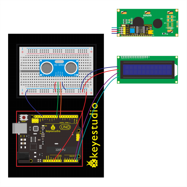
Check out the circuit diagram and hookup table below to see how everything is connected.
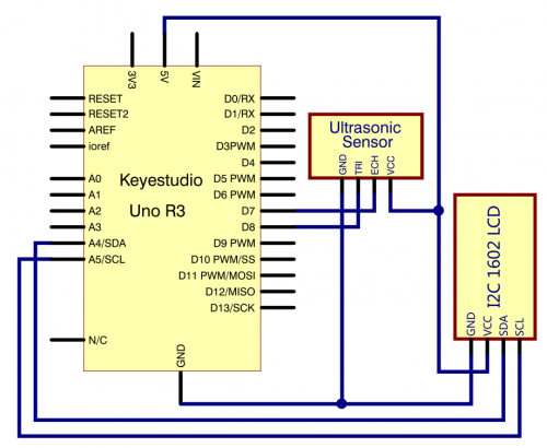
Upload Code:
- 1) Note: Before you can run this, make sure that you have installed the LCD library or re-install it, if necessary. Otherwise, your code won't work.
- 2)Connect the REV4 Board to a USB port on your computer.
- 3)Open the program in the code folder- Circuit 17, or directly copy and paste the code below on the Ardunio IDE.
- 4)Select UPLOAD to program the sketch on the REV4 Board.
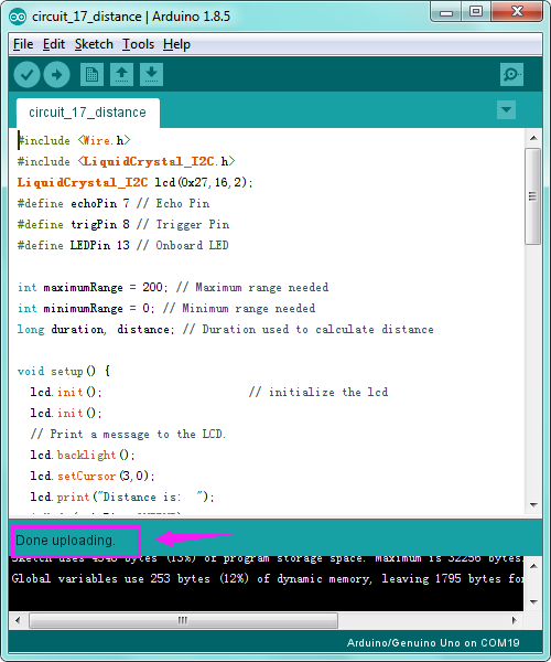
#include <Wire.h>
#include <LiquidCrystal_I2C.h>
LiquidCrystal_I2C lcd(0x27,16,2);
#define echoPin 7 // Echo Pin
#define trigPin 8 // Trigger Pin
#define LEDPin 13 // Onboard LED

int maximumRange = 200; // Maximum range needed
int minimumRange = 0; // Minimum range needed
long duration, distance; // Duration used to calculate distance

void setup() {
  lcd.init();                      // initialize the lcd
  lcd.init();
  // Print a message to the LCD.
  lcd.backlight();
  lcd.setCursor(3,0);
  lcd.print("Distance is:  ");
 pinMode(trigPin, OUTPUT);
 pinMode(echoPin, INPUT);
 pinMode(LEDPin, OUTPUT); // Use LED indicator (if required)
}

void loop() {
/* The following trigPin/echoPin cycle is used to determine the
 distance of the nearest object by bouncing soundwaves off of it. */
 digitalWrite(trigPin, LOW);
 delayMicroseconds(2);

 digitalWrite(trigPin, HIGH);
 delayMicroseconds(10);
 digitalWrite(trigPin, LOW);

 duration = pulseIn(echoPin, HIGH);

 //Calculate the distance (in cm) based on the speed of sound.
 distance = duration/58.2;

 if (distance >= maximumRange || distance <= minimumRange){
 /* Send a negative number to computer and Turn LED ON
 to indicate "out of range" */
  lcd.setCursor(3,1);
  lcd.print("-1   ");
 digitalWrite(LEDPin, HIGH);
 }
 else {
 /* turn LED OFF to indicate successful reading. */
  lcd.setCursor(3,1);
  lcd.print(distance);
 digitalWrite(LEDPin, LOW);
 }
 if(distance<10)
 {
  lcd.setCursor(4,1);
  lcd.print("    ");
}
 if(distance<100)
 {
  lcd.setCursor(5,1);
  lcd.print("    ");
}
 //Delay 50ms before next reading.
 delay(50);
}
What You Will See:
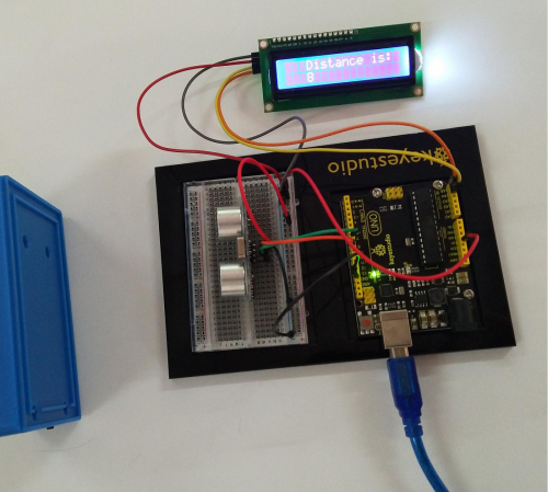
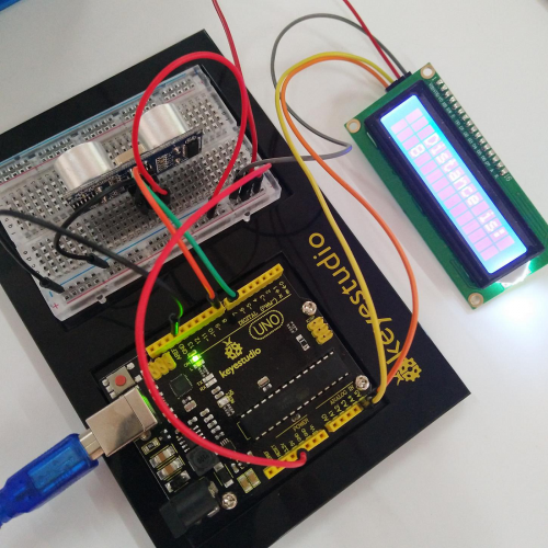
Move your hand or a large, flat object closer and farther away from the distance sensor.
As the object approaches, the LCD display screen will show the distance being read from the sensor.
Troubleshooting:
- LCD Display Not Clear?
Remember you can adjust the contrast using the potentiometer if you can’t make out the words clearly.

Circuit 18: Driving Servo Motor
About this circuit:
In this circuit, you will learn how to wire a servo and control it with code. Servo motors can be told to move to a specific position and stay there. Here we will turn a potentiometer to make the servo rotate in a certain angle.
What You Need:
- REV4 Baseplate
- Servo motor x 1
- Potentiometer x 1
- Jumper wires x 8
- USB cable x 1
Component Introduction:
Servo motor:
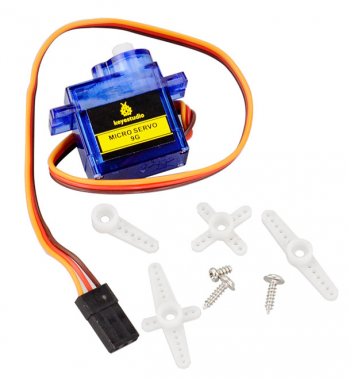
The servo has three interfaces,distinguished by brown, red and orange line (different brand may have different color).
Brown line is for GND, red one for power 5V, orange one for signal terminal (PWM signal).
Included with your servo motor you will find a variety of white motor mounts that connect to the shaft of your servo.
You may choose to attach any mount you wish for the circuit. It will serve as a visual aid, making it easier to see the servo spin.
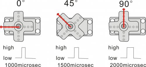
The rotation angle of servo is controlled by regulating the duty cycle of the PWM(Pulse-Width Modulation) signal. The standard cycle of the PWM signal is fixed at 20ms (50 Hz), and the pulse width is distributed between 1ms-2ms. The pulse width corresponds to the rotation angle ( 0°~90°) of servo.
Hookup Guide:
Check out the circuit diagram and hookup table below to see how everything is connected.
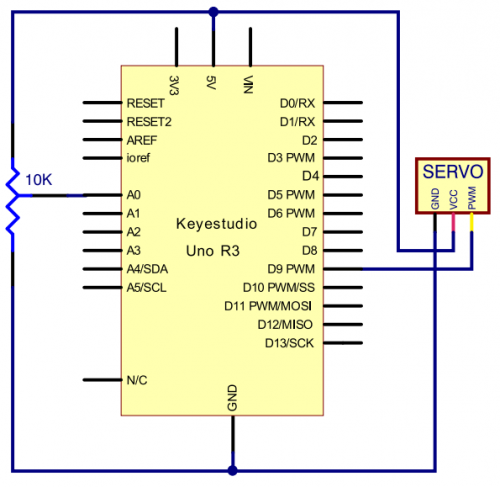
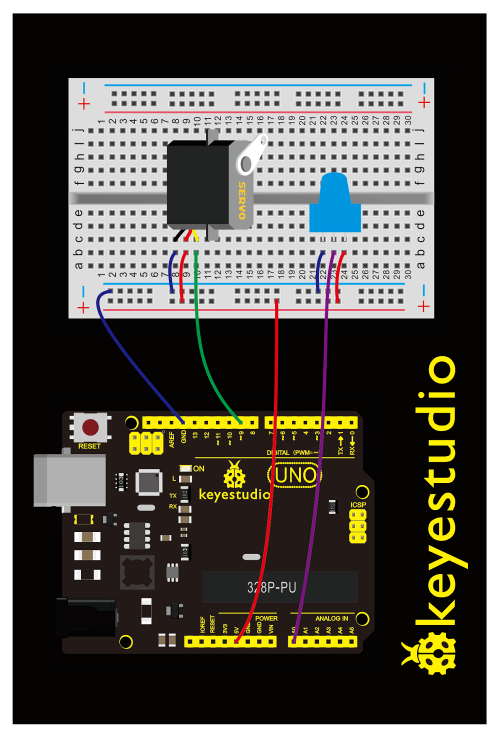
Upload Code:
- 1) Note: Before you can run this, make sure that you have installed the <Servo.h> library or re-install it, if necessary. Otherwise, your code won't work.
- 2)Connect the REV4 Board to a USB port on your computer.
- 3)Open the program in the code folder- Circuit 18, or directly copy and paste the code below on the Ardunio IDE.
- 4)Select UPLOAD to program the sketch on the REV4 Board.
#include <Servo.h>
Servo myservo;//define steering engine variable
int servo =0;
void setup()
{
 Serial.begin(9600); // 9600 bps
 myservo.attach(9);//define steering engine interface(alternative 9 and 10 but just able to control 2interfaces)
}
void loop()
{
servo=map ( analogRead(0) , 0 , 1023 , 0 , 180 )  ;
Serial.println(servo ,DEC);
myservo.write(servo);//set rotating angle
delay(50);
}
Code Explanation:
- Single line comments start with // and everything up until the end of that line is considered a comment.
Comments are a great way to leave notes in your code explaining why you wrote it the way you did.
- The first line of source code is:
#include <Servo.h>
The #include command adds a library to your Arduino program. After you include a library, you can use the commands in the library in your program.
- myservo.attach(9)
It tells the servo object to which pin the signal wire is attached. It will send position signals to this pin. In this sketch, pin 9 is used.
What You Will See:
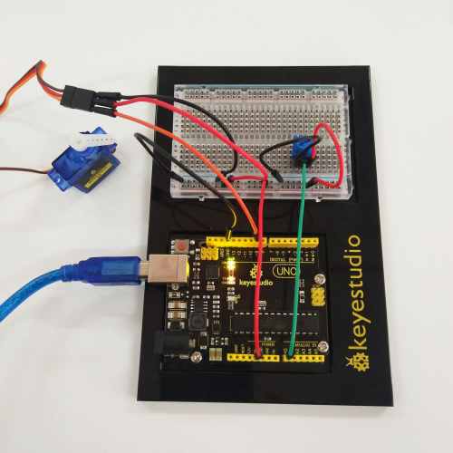
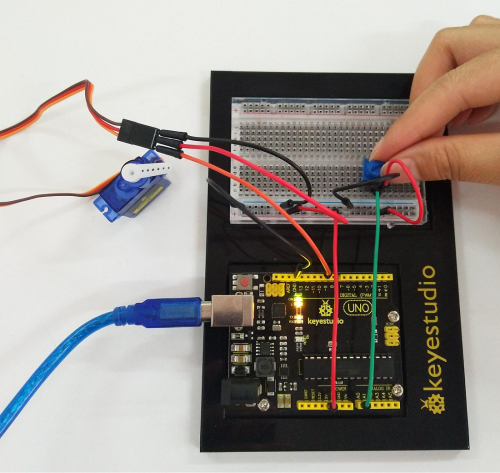
Turning the potentiometer will cause the servo arm to turn. The servo will mimic the movement of the potentiometer, twisting in the same clockwise or counter-clockwise direction.
If you’ve attached a white mount to the servo, this movement will be easier to see. Also can check out the angle value on the serial monitor.
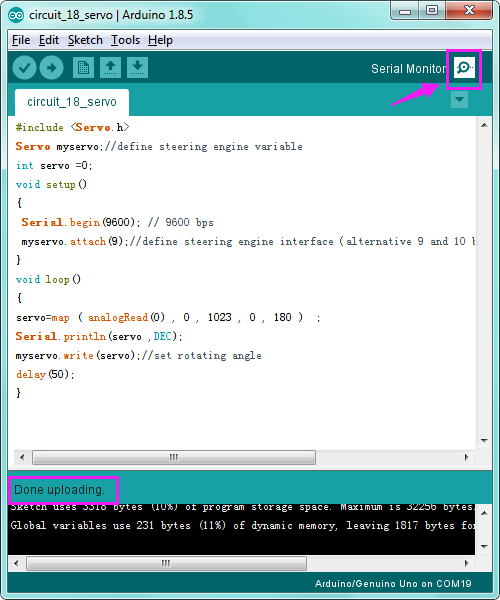
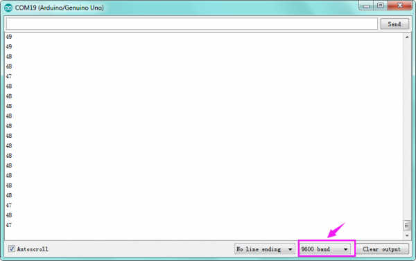
Circuit 19: Relay
About this circuit:
In this circuit, you will learn how to use a relay and other tiny sensors to turn on an LED.
What You Need:
- REV4 Baseplate
- Relay x 1
- 4N35 *1
- 4007 Diode*1
- 8050 Transistor *1
- Red LED x 1
- 220Ω Resistor x 2
- Jumper wires x 11
- USB cable x 1
Component Introduction:
Relay:
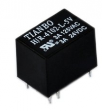 A relay is basically an electrically controlled mechanical switch with isolation function.
Relays are used where it is necessary to control a circuit by a low power signal (with complete electrical isolation between control and controlled circuits), or where several circuits must be controlled by one signal.
It's widely used in remote control, remote sensing, communication, automatic control, and electronic devices. It is one of the most important control elements.
4N35 IC:
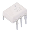 The 4N35 is a general-purpose optocoupler that contains a gallium arsenide infrared light-emitting diode, which is used to drive silicon phototransistors.
4007 Diode:
Used to protect the circuit
![]()
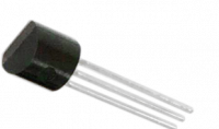
NPN 8050 Transistor:
Used as a switch
Hookup Guide:
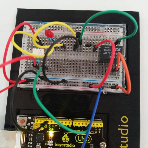
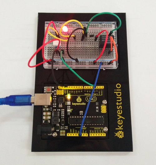
Check out the circuit diagram and hookup table below to see how everything is connected.
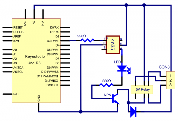
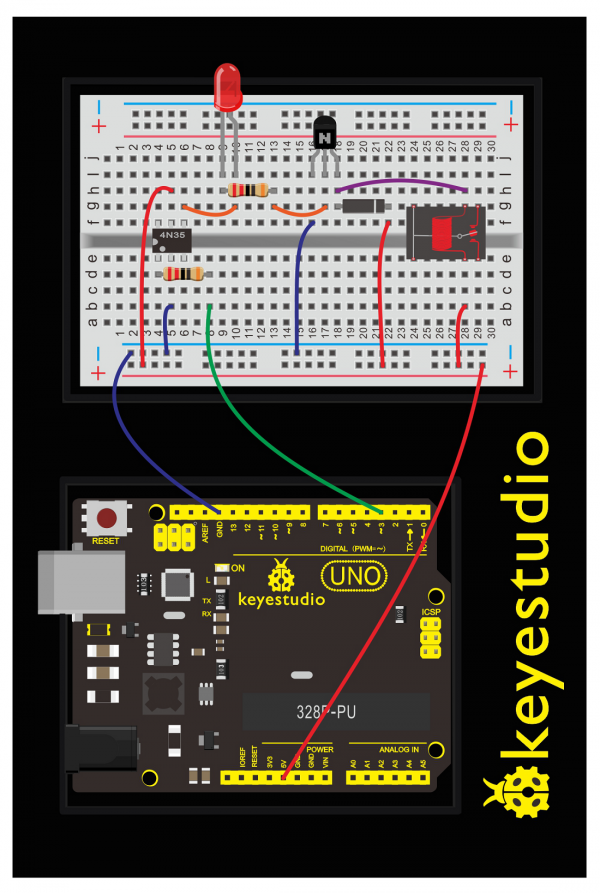
(pay attention to using the NPN 8050 transistor; the plug direction of 4N35, relay and diode )
Upload Code:
- 1)Connect the REV4 Board to a USB port on your computer.
- 2)Open the program in the code folder- Circuit 19, or directly copy and paste the code below on the Ardunio IDE.
- 3)Select UPLOAD to program the sketch on the REV4 Board.
int relay = 3; // relay turn-on trigger signal - active high;
void setup ()
{
pinMode (relay, OUTPUT); //define port attribute for the output;
}
void loop ()
{
digitalWrite (relay, HIGH); // relay conducted;
delay (1000);
digitalWrite (relay, LOW); // relay switch;
delay (1000);
}
What You Will See:
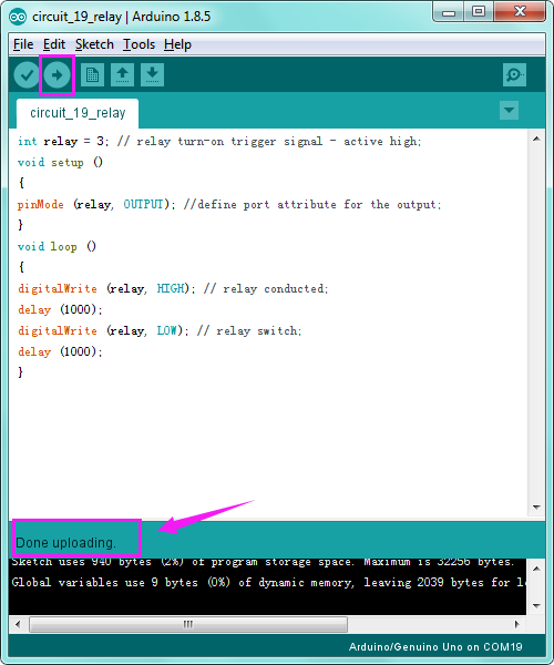
Here, when S is in high level, relay switches to the ON end. LED will be turned on.
In the test result, you should be able to hear the relay contacts click, and see the LED turning on and off at 1-second intervals.
Troubleshooting:
- LED Not Lighting?
Double-check that you have plugged them in correctly. The longer lead is the positive end.
- No Clicking Sound?
Check the transistor you use is NPN8050, whether plug in the right way.
Circuit 20: PIR Motion Sensor
About this circuit: In this lesson we will create an alarm system to detect motion, combining usage of PIR sensor, 1602 LCD and LED.
What You Need:
- REV4 Baseplate
- PIR motion sensor x 1
- 1602 LCD display x 1
- Red LED x 1
- 220Ω Resistor x 1
- M-M Jumper wires x 7
- M-F Jumper wires x 3
- USB cable x 1
Component Introduction:
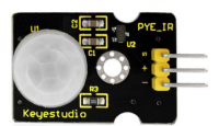
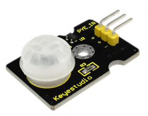
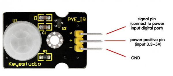
PIR motion sensor:
The Pyroelectric infrared motion sensor can detect infrared signals from a moving person or moving animal, and output switching signals. It can be applied to a variety of occasions to detect the movement of human body.
Parameters:
- Input Voltage: DC 3.3V ~ 18V
- Working Current: 15uA
- Working Temperature: -20 ~ 85 ℃
- Output Voltage: High 3V, Low 0V
- Output Delay Time (High Level): About 2.3 to 3 Seconds
- Detection Angle: 100°
- Detection Distance: 7 meters
- Output Indicator LED (If it is HIGH level, it will be ON)
- Pin Limit Current: 100mA
Hookup Guide:
Check out the circuit diagram and hookup table below to see how everything is connected.
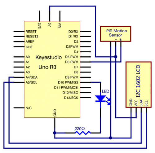
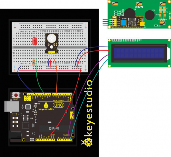
Upload Code:
- 1) Note: Before you can run this, make sure that you have installed the LCD library or re-install it, if necessary. Otherwise, your code won't work.
- 2)Connect the REV4 Board to a USB port on your computer.
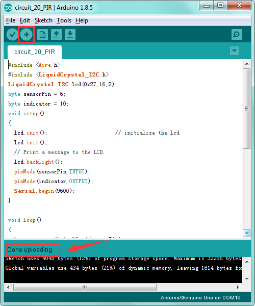
- 3)Open the program in the code folder- Circuit 20, or directly copy and paste the code below on the Ardunio IDE.
- 4)Select UPLOAD to program the sketch on the REV4 Board.
#include <Wire.h>
#include <LiquidCrystal_I2C.h>
LiquidCrystal_I2C lcd(0x27,16,2);
byte sensorPin = 6;
byte indicator = 10;
void setup()
{
  lcd.init();                      // initialize the lcd
  lcd.init();
  // Print a message to the LCD.
  lcd.backlight();
  pinMode(sensorPin,INPUT);
  pinMode(indicator,OUTPUT);
  Serial.begin(9600);
}

void loop()
{
  byte state = digitalRead(sensorPin);
  digitalWrite(indicator,state);
  if(state == 1)
  {
  lcd.setCursor(2,0);
  lcd.print("Somebody is");
  lcd.setCursor(2,1);
  lcd.print("in this area!");
  }
  else if(state == 0)
  {
  lcd.setCursor(2,0);
  lcd.print("No one!      ");
  lcd.setCursor(2,1);
  lcd.print("No one!      ");
  delay(500);
  }
}
What You Will See:
Move your hand or a large, flat object closer and farther away from the PIR sensor.
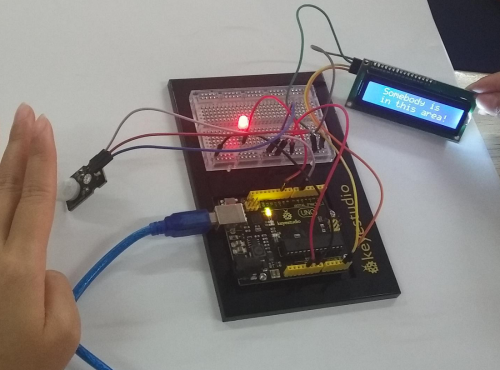
If the LCD shows ”Somebody is in this area!” and LED lights up, it is reminding of you that somebody is here.
Otherwise, it will tell you by displaying “No one!”on LCD and LED off.
Troubleshooting:
- LED Not Lighting?
Double-check that you have plugged them in correctly. Make sure the connection no wrong.
- LCD Display Not Clear?
Remember you can adjust the contrast using the potentiometer if you can’t make out the words clearly.

GET STARTED WITH ROBOT PROJECTS!
In this project, you will learn all about DC motors and motor drivers by building your own robot!
You’ll first learn motor control basics.By adding an IR receiver, remote control the robot to move freely.
By adding an IR receiver or distance sensor, the robot can learn how to avoid obstacles.
ROBOT BASEPALTE ASSEMBLY
Before you build this circuit, you’ll need to make a few modifications to the breadboard baseplate to make it more robot-like!
1. Cut two more strips and weld the strips to the two motors.
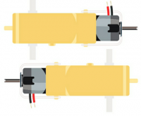
Cut and attach two short pieces of dual-lock adhesive tape to your motors. Be sure that your motors are mirror images of each other when you attach the Dual Lock tape.
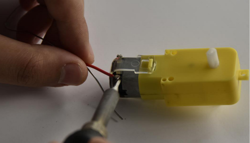
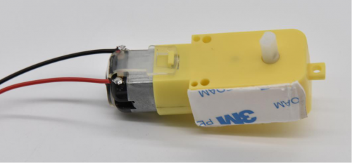
2. Press the motor to the baseplate, connecting the Dual Lock surfaces. Try to get the motors as straight as possible so your robot will drive straight.
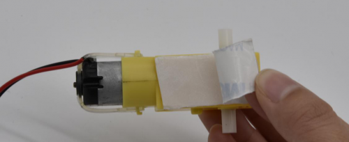
Make sure the Omni-directional wheel is firmly mounted on the Clear Acrylic plate with the two screws and nuts.
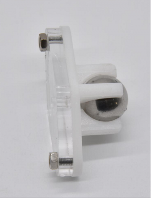
Then cut and attach a short piece of dual-lock adhesive tape to Acrylic plate.
Stick the two motors and Omni-directional wheel on the keyestudio Baseplate.
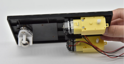
3. The bottom of your baseplate should look like the image. Remember that the two motors should be mirror images of each other.
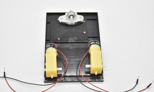
4.Attach the wheels by sliding them onto the plastic shafts on the gear motor. The shaft is flat on one side, as is the wheel coupler.
Align the two, and then press to fit the wheel onto the shaft.
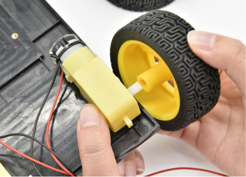
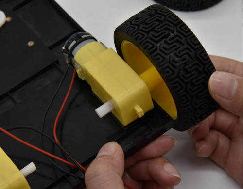
5.The white part will act as a caster as the robot drives around.
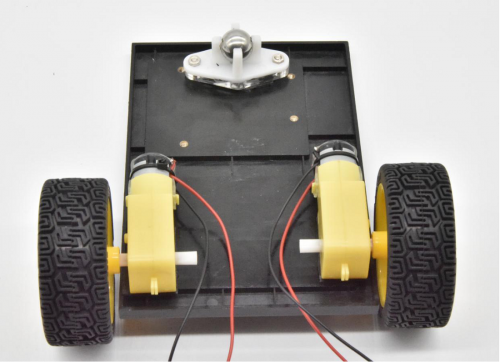
Battery Holder Attachment:
Cut two pieces of Dual Lock. Remove the adhesive backing, and attach one piece to the back of the battery holder.
Adhere the second piece to the bottom of the baseplate, directly in the middle. Press the battery holder to the baseplate so that the two pieces of Dual Lock snap together.
Insert the batteries into the holder if you have not done so already.
Remember that batteries are polarized and can only go in one way.
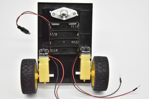
Once you’re finished, it’s time to build the circuit.
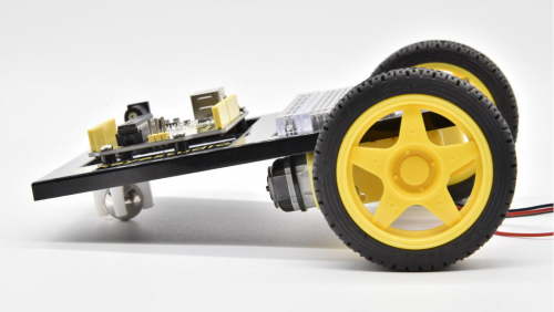
Circuit 21: Motor Basics
About this circuit:
In this circuit, you will learn the basic concepts behind motor control.
You’ll use what is known as a motor controller or motor driver board to power and spin the motor accordingly.
What You Need:
- Gear Motor x 2
- TB6612FNG Motor Driver x 1
- Slide switch x 1
- Jumper wires x 21
Component Introduction:
Gear Motor:
The gear motor has two main parts: a small DC motor that spins quickly and a plastic gearbox that gears down the output from the hobby motor so that it is slower but stronger, allowing it to move your robot.
TB6612FNG Motor Driver:
The TB6612FNG Motor Driver may look complicated, but it’s easy to use. The TB6612FNG motor driver can control up to two DC motors at a constant current of 1.2A (3.2A peak).
Two input signals (IN1 and IN2) can be used to control the motor in one of four function modes - CW, CCW, short-brake, and stop.
The two motor outputs (A and B) can be separately controlled; speed of each motor is controlled via a PWM input signal with a frequency up to 100kHz.
The STBY pin should be pulled high to take the motor out of standby mode.
Logic supply voltage (VCC) can be in the range of DC 2.7-5.5V, while the motor supply (VM) is limited to a maximum voltage of 15V DC.
The output current is rated up to 1.2A per channel (or up to 3.2A for a short, single pulse).
The motor driver pins are explained in the table below.
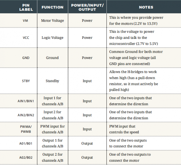
Features:
- Power supply voltage: VM=15V max, VCC=2.7-5.5V
- Output current: Iout=1.2A(average) / 3.2A (peak)
- Standby control to save power
- CW/CCW/short brake/stop motor control modes
- Built-in thermal shutdown circuit and low voltage detecting circuit
- Filtering capacitors on both supply lines
Slide switch:
SWITCHES are components that control the open-ness or closed-ness of an electric circuit.
Just like the momentary buttons used in earlier circuits, this type of switch can only exist in one of two states: open or closed.
However, a switch is different in that it will stay in the position it was last in until it is switched again.
Hookup Guide:
Check out the circuit diagram and hookup table below to see how everything is connected.
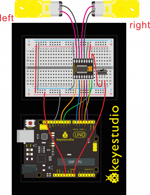
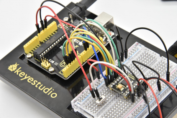
Upload Code:
- 1)Connect the REV4 Board to a USB port on your computer.
- 2)Open the program in the code folder- Circuit 21, or directly copy and paste the code below on the Ardunio IDE.
- 3)Select UPLOAD to program the sketch on the REV4 Board.
- 4)Unplug the USB cable, then power the board with 7-12V battery pack.
Code 1:
int AIN1=2;
int AIN2=3;
int STBY=4;
int BIN1=5;
int BIN2=6;
int PWMA=10;// enable pin 1
int PWMB=11;// enable pin 2
// D2 and D3 as a set, D5 and D6 as a set
// D10 and D11 as enable pins for DC motors
void setup()
{
  int i;
  for (i=2;i<=6;i++) // Ardunio motor driver module
  pinMode(i,OUTPUT); // set digital pins 2,3,4,5,6 as output
  pinMode(10,OUTPUT);// set digital pins 10, 11 as output
  pinMode(11,OUTPUT);
}
void loop()
{
  // 2 DC motor rotate CW for 1S, and rotate CCW for 1S
  // rotate CW
  front();
  delay(1000);
  Stop();
  back();
  delay(1000);
  Stop();
  delay(1000);
  left();
  delay(1000);
  Stop();
  delay(1000);
  right();
  delay(1000);
  Stop();
  delay(1000);
}
void front() {
    digitalWrite(STBY,HIGH);
    digitalWrite(AIN1,HIGH);
    digitalWrite(AIN2,LOW);
    analogWrite(PWMA,200);
    digitalWrite(BIN1,HIGH);
    digitalWrite(BIN2,LOW);
    analogWrite(PWMB,200);
}

void back() {
    digitalWrite(STBY,HIGH);
    digitalWrite(AIN1,LOW);
    digitalWrite(AIN2,HIGH);
    analogWrite(PWMA,200);
    digitalWrite(BIN1,LOW);
    digitalWrite(BIN2,HIGH);
    analogWrite(PWMB,200);
}

void Stop() {
  digitalWrite(STBY,LOW);
}

void left() {

    digitalWrite(STBY,HIGH);
    digitalWrite(AIN1,HIGH);
    digitalWrite(AIN2,LOW);
    analogWrite(PWMA,200);
    digitalWrite(BIN1,LOW);
    digitalWrite(BIN2,HIGH);
    analogWrite(PWMB,200);
}

void right() {
    digitalWrite(STBY,HIGH);
    digitalWrite(AIN1,LOW);
    digitalWrite(AIN2,HIGH);
    analogWrite(PWMA,200);
    digitalWrite(BIN1,HIGH);
    digitalWrite(BIN2,LOW);
    analogWrite(PWMB,200);
}
Code 2:
int AIN1=2;
int AIN2=3;
int STBY=4;
int BIN1=5;
int BIN2=6;
int PWMA=10;// enable pin 1
int PWMB=11;// enable pin 2
// D2 and D3 as a set, D5 and D6 as a set
// D10 and D11 as enable pins for DC motors
void setup()
{
  int i;
  for (i=2;i<=6;i++) // Ardunio motor driver module
  pinMode(i,OUTPUT); // set digital pins 2,3,4,5,6 as output
  pinMode(10,OUTPUT);// set digital pins 10, 11 as output
  pinMode(11,OUTPUT);
}
void loop()
{
  // 2 DC motor rotate CW for 1S, and rotate CCW for 1S
  // rotate CW
   digitalWrite(STBY,HIGH);

   digitalWrite(AIN1,HIGH);
   digitalWrite(AIN2,LOW);
   analogWrite(PWMA,200);
   digitalWrite(BIN1,HIGH);
   digitalWrite(BIN2,LOW);
   analogWrite(PWMB,200);
   delay(1000);
  // pause for 1S
   digitalWrite(STBY,LOW);
   delay(1000);
  // rotate CCW
    digitalWrite(STBY,HIGH);
    digitalWrite(AIN1,LOW);
    digitalWrite(AIN2,HIGH);
    analogWrite(PWMA,200);
    digitalWrite(BIN1,LOW);
    digitalWrite(BIN2,HIGH);
    analogWrite(PWMB,200);
delay(1000);
// pause for 1S
   digitalWrite(STBY,LOW);
   delay(1000);
}
What You Will See:
Uploaded well the code, and flip the switch. The motor will spin at the speed set by the motor speed variable.
Here in the folder we provide two codes for the same wiring method.
If upload the code 1 motor basics, the motor will rotate forward for one second then stop for one second; then go back for one second and stop for one second; followed by turning left for 1S, stop for 1S then turn right for 1S and stop for 1S repeatedly and circularly.
If upload the code 2 motor drive, the motor will rotate forward for one second then stop for one second, followed by turning backward for one second and stop for one second, repeatedly and circularly.
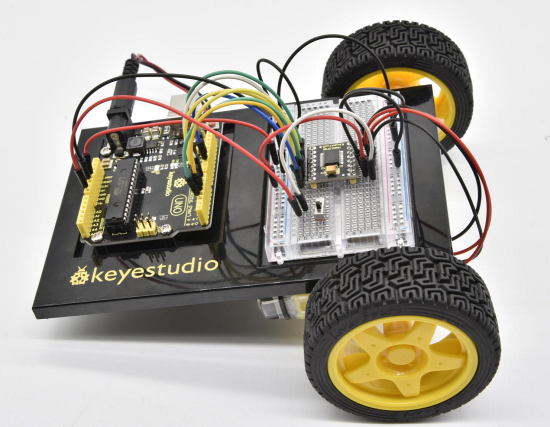
Circuit 22: Light Following Robot
About this circuit:
Using two photo-resistors are a great way to have light control of your project. In this circuit, you’ll control two motors and build your own light following robot!
You can use the light source to tell the robot in what direction to move or move straight.
What You Need:
- Gear Motor x 2
- TB6612FNG Motor Driver x 1
- Slide switch x 1
- Photo resistor x 2
- 10KΩ Resistor x 2
- Jumper wires x 21
Component Introduction:
Photo Resistor:
Photo resistor (Photovaristor) is a resistor whose resistance varies according to different incident light strength.
It's made based on the photoelectric effect of semiconductor.
If the incident light is intense, its resistance reduces; if the incident light is weak, the resistance increases.
Photo resistor is widely applied to various light control circuit, such as light control and adjustment, optical switches, etc.

Hookup Guide:
Check out the circuit diagram and hookup table below to see how everything is connected.
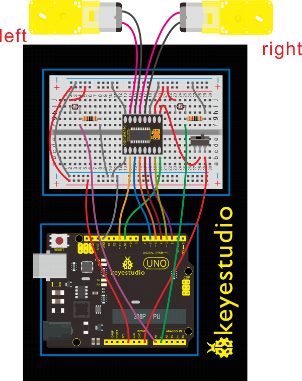
Upload Code:
- 1)Connect the REV4 Board to a USB port on your computer.
- 2)Open the program in the code folder- Circuit 22, or directly copy and paste the code below on the Ardunio IDE.
- 3)Select UPLOAD to program the sketch on the REV4 Board.
int value1=0;
int value2=0;
int AIN1=2;
int AIN2=3;
int STBY=4;
int BIN1=5;
int BIN2=6;
int PWMA=10;// enable pin 1
int PWMB=11;// enable pin 2
int Fspeed;
int Lspeed;
int Rspeed;
void setup()
 {
  Serial.begin(9600);
  int i;
  for (i=2;i<=6;i++) // Ardunio motor driver module
  pinMode(i,OUTPUT); // set digital pins 2,3,4,5,6 as output
  pinMode(10,OUTPUT);// set digital pins 10, 11 as output
  pinMode(11,OUTPUT);

 }

void loop()
    {
     value1=analogRead(0);
     value2=analogRead(1);
     Serial.print(value1);
     Serial.print("  ");
     Serial.println(value2);
     if(value1 >900&&value2 >900)         //if front distance is less than 10cm
     {
      front();
      }
     if(value1 >900&&value2 <=900)         //if front distance is less than 10cm
     {
      left();
      }
     if(value1 <=900&&value2 >900)         //if front distance is less than 10cm
     {
      right();
      }
       if(value1 <=900&&value2 <=900)         //if front distance is less than 10cm
     {
      stop();
      }
    }
void front() {
    digitalWrite(STBY,HIGH);
    digitalWrite(AIN1,HIGH);
    digitalWrite(AIN2,LOW);
    analogWrite(PWMA,200);
    digitalWrite(BIN1,HIGH);
    digitalWrite(BIN2,LOW);
    analogWrite(PWMB,200);
}

void back() {
    digitalWrite(STBY,HIGH);
    digitalWrite(AIN1,LOW);
    digitalWrite(AIN2,HIGH);
    analogWrite(PWMA,200);
    digitalWrite(BIN1,LOW);
    digitalWrite(BIN2,HIGH);
    analogWrite(PWMB,200);
}

void stop() {
  digitalWrite(STBY,LOW);
}

void left() {

    digitalWrite(STBY,HIGH);
    digitalWrite(AIN1,HIGH);
    digitalWrite(AIN2,LOW);
    analogWrite(PWMA,200);
    digitalWrite(BIN1,LOW);
    digitalWrite(BIN2,HIGH);
    analogWrite(PWMB,200);
}

void right() {
    digitalWrite(STBY,HIGH);
    digitalWrite(AIN1,LOW);
    digitalWrite(AIN2,HIGH);
    analogWrite(PWMA,200);
    digitalWrite(BIN1,HIGH);
    digitalWrite(BIN2,LOW);
    analogWrite(PWMB,200);
}
What You Will See
Start by flipping the switch to the ON position.
Hook it up and upload the code success, the tank robot is walking with strong light under certain illumination.
When one photoresistor senses the light source, the robot will turn round then follow the light illumination.
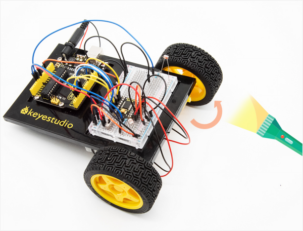
Both two photoresistors sense the light source, the robot will go straight to follow the light illumination. Shown below.
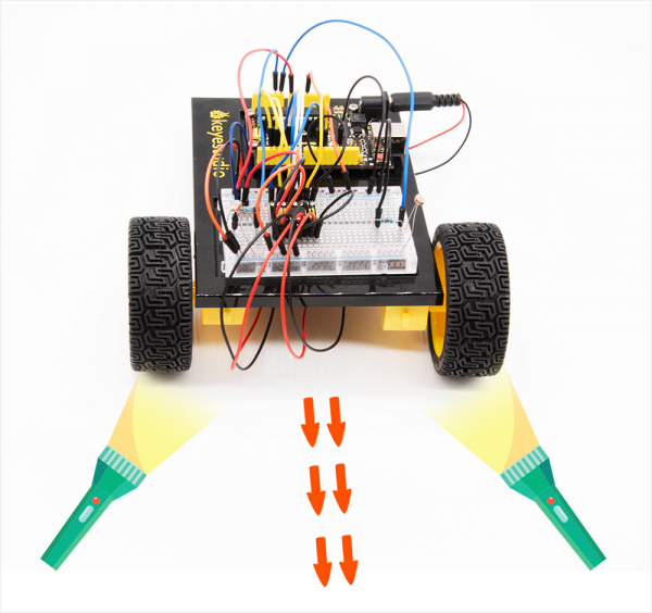
Circuit 23: Remote-Controlled Robot
About this circuit:
Using an IR Remote is a great way to have wireless control of your project. In this circuit, you’ll control two motors and build your own remote-controlled roving robot!
You can use the remote controller to tell the robot in what direction to move and how far to move.
What You Need:
- Gear Motor x 2
- TB6612FNG Motor Driver x 1
- Slide switch x 1
- IR receiver x 1
- Remote controller x 1
- Jumper wires x 24
Component Introduction:
IR Receiver:
Infrared receiver is a component with functions of reception, amplification, and demodulation.
The internal IC has already been demodulated so that can directly output digital signal.
Infrared receiver has 3 pins. When you use it, connect VOUT to Analog pin, GND to GND, VCC to +5V.

Remote Controller:
Infrared remote control is composed of infrared transmitting and infrared receiving systems.
That is, consist of an infrared remote control, an infrared receiver module and a micro-controller that can decode.
You can refer to the figure below.

Below we have listed out each button value of keyestudio remote control for reference.
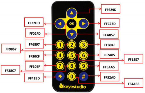
Hookup Guide:
Check out the circuit diagram and hookup table below to see how everything is connected.
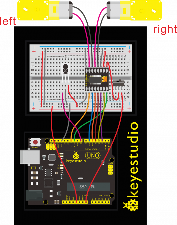
Upload Code:
- 1) Note: Before you can run this, make sure that you have installed the <IRremote.h> library or re-install it, if necessary. Otherwise, your code won't work.
- 2)Connect the REV4 Board to a USB port on your computer.
- 3)Open the program in the code folder- Circuit 23, or directly copy and paste the code below on the Ardunio IDE.
- 4)Select UPLOAD to program the sketch on the REV4 Board.
#include <IRremote.h>
int RECV_PIN = 8;
int LED1 = 13;
unsigned long on1  = 0x00FF6897;
unsigned long off1 = 0x00FF9867;
int AIN1=2;
int AIN2=3;
int STBY=4;
int BIN1=5;
int BIN2=11;
int PWMA=10;// enable pin 1
int PWMB=6;// enable pin 2
unsigned long advance1 = 0x00FF629D;
unsigned long back1 = 0x00FFA857;
unsigned long stop1 = 0x00FF02FD;
unsigned long left1 = 0x00FF22DD;
unsigned long right1 = 0x00FFC23D;
IRrecv irrecv(RECV_PIN);
decode_results results;
void setup()
 {
  int i;
  for (i=2;i<=6;i++) // Ardunio motor driver module
  pinMode(i,OUTPUT); // set digital pins 2,3,4,5,6 as output
  pinMode(10,OUTPUT);// set digital pins 10, 11 as output
  pinMode(11,OUTPUT);
  pinMode(LED1, OUTPUT);
  irrecv.enableIRIn(); // Start the receiver
 }
void loop()
{
  if (irrecv.decode(&results))
   {
    if (results.value == advance1 )
       front();
    if (results.value == back1 )
       back();
    if (results.value == stop1)
       Stop();
    if (results.value == left1 )
       left();
    if (results.value == right1 )
       right();
    if (results.value == on1 )
       digitalWrite(LED1, HIGH);
    if (results.value == off1 )
       digitalWrite(LED1, LOW);
    irrecv.resume(); // Receive the next value
  }
}
void front() {
    digitalWrite(STBY,HIGH);
    digitalWrite(AIN1,HIGH);
    digitalWrite(AIN2,LOW);
    analogWrite(PWMA,200);
    digitalWrite(BIN1,HIGH);
    digitalWrite(BIN2,LOW);
    analogWrite(PWMB,200);
}

void back() {
    digitalWrite(STBY,HIGH);
    digitalWrite(AIN1,LOW);
    digitalWrite(AIN2,HIGH);
    analogWrite(PWMA,200);
    digitalWrite(BIN1,LOW);
    digitalWrite(BIN2,HIGH);
    analogWrite(PWMB,200);
}

void Stop() {
  digitalWrite(STBY,LOW);
}

void left() {

    digitalWrite(STBY,HIGH);
    digitalWrite(AIN1,HIGH);
    digitalWrite(AIN2,LOW);
    analogWrite(PWMA,200);
    digitalWrite(BIN1,LOW);
    digitalWrite(BIN2,HIGH);
    analogWrite(PWMB,200);
}

void right() {
    digitalWrite(STBY,HIGH);
    digitalWrite(AIN1,LOW);
    digitalWrite(AIN2,HIGH);
    analogWrite(PWMA,200);
    digitalWrite(BIN1,HIGH);
    digitalWrite(BIN2,LOW);
    analogWrite(PWMB,200);
}
What You Will See
Start by flipping the switch to the ON position. Use remote control to make the robot move or turn.
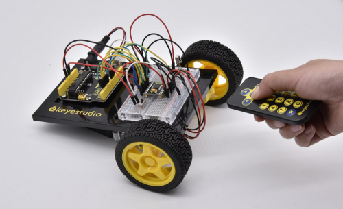
Circuit 24: Ultrasonic Ranging Robot
About this circuit:
In this circuit, you’ll control two motors and build your own obstacle avoidance robot! The robot that you will build uses a simple sensor to avoid obstacles.
What You Need:
- Gear Motor x 2
- TB6612FNG Motor Driver x 1
- Slide switch x 1
- ultrasonic sensor x 1
- Jumper wires x 25
Hookup Guide:
Check out the circuit diagram and hookup table below to see how everything is connected.
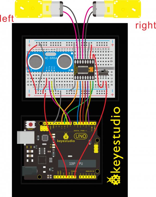
Upload Code:
- 1)Connect the REV4 Board to a USB port on your computer.
- 2)Open the program in the code folder- Circuit 24, or directly copy and paste the code below on the Ardunio IDE.
- 3)Select UPLOAD to program the sketch on the REV4 Board.
int AIN1=2;
int AIN2=3;
int STBY=4;
int BIN1=5;
int BIN2=6;
int PWMA=10;// enable pin 1
int PWMB=11;// enable pin 2
int pinTrip = 8;  //define ultrasonic ting pin to D12
int pinEcho = 9;   //define ultrasonic echo pin to D13
int Fspeed;
int Lspeed;
int Rspeed;
void setup()
 {
  Serial.begin(9600);
  int i;
  for (i=2;i<=6;i++) // Ardunio motor driver module
  pinMode(i,OUTPUT); // set digital pins 2,3,4,5,6 as output
  pinMode(10,OUTPUT);// set digital pins 10, 11 as output
  pinMode(11,OUTPUT);
  pinMode(pinTrip,OUTPUT);
  pinMode(pinEcho,INPUT);

 }
 void ask_pin_F()   // measure the front distance
    {
      digitalWrite(pinTrip, LOW);   //  make ultrasonic emit LOW voltage 2μs
      delayMicroseconds(2);
      digitalWrite(pinTrip, HIGH);  // make ultrasonic emit HIGH voltage 10μs,here at least 10μs
      delayMicroseconds(10);
      digitalWrite(pinTrip, LOW);    // make ultrasonic emit LOW voltage
      float Fdistance = pulseIn(pinEcho, HIGH);  // read the time difference
      Fdistance= Fdistance/5.8/10;       // turn time into distance (unit:cm)
      Fspeed = Fdistance;              // read distance into Fspeedd(front speed)
      Serial.print("Fspeed = ");
      Serial.print(Fspeed );
      Serial.println("  cm");
    }
void loop()
    {
      ask_pin_F();            // read the front distance
     if(Fspeed < 10)         //if front distance is less than 10cm       {
      stop();               // clear the output data
      delay(100);
      back();                // backward 0.2 second
      delay(200);
      }

      if(Fspeed < 25)         //if front distance is less than25cm
      {
        stop();
        left();
        delay(200);             // clear the output data
        ask_pin_F();            // read the front distance
        Lspeed = Fspeed;
        right();
        delay(400);
        ask_pin_F();            //read the front distance
        Rspeed = Fspeed;

        if(Lspeed > Rspeed)   //if left speed is greater than right speed
        {
        left();
        delay(400);
        front();
        }

        if(Lspeed <= Rspeed)   //if left speed is less than or equal to right speed
        {
         front();
        }

        if (Lspeed < 10 && Rspeed < 10)   //if both left and right side distance are less than 10cm
        {
         back();      //go back
        }
      }
      else                      //if front distance is within 25cm
      {
       front();
      }
    }
void front() {
    digitalWrite(STBY,HIGH);
    digitalWrite(AIN1,HIGH);
    digitalWrite(AIN2,LOW);
    analogWrite(PWMA,200);
    digitalWrite(BIN1,HIGH);
    digitalWrite(BIN2,LOW);
    analogWrite(PWMB,200);
}

void back() {
    digitalWrite(STBY,HIGH);
    digitalWrite(AIN1,LOW);
    digitalWrite(AIN2,HIGH);
    analogWrite(PWMA,200);
    digitalWrite(BIN1,LOW);
    digitalWrite(BIN2,HIGH);
    analogWrite(PWMB,200);
}

void stop() {
  digitalWrite(STBY,LOW);
}

void left() {

    digitalWrite(STBY,HIGH);
    digitalWrite(AIN1,HIGH);
    digitalWrite(AIN2,LOW);
    analogWrite(PWMA,200);
    digitalWrite(BIN1,LOW);
    digitalWrite(BIN2,HIGH);
    analogWrite(PWMB,200);
}

void right() {
    digitalWrite(STBY,HIGH);
    digitalWrite(AIN1,LOW);
    digitalWrite(AIN2,HIGH);
    analogWrite(PWMA,200);
    digitalWrite(BIN1,HIGH);
    digitalWrite(BIN2,LOW);
    analogWrite(PWMB,200);
}
The robot that you will build uses a simple sensor to avoid obstacles.
Keep in mind that the ultrasonic distance sensor needs a clear path to avoid unwanted interruptions in your robot’s movements.
Keep the distance sensor clear of any wires from your circuit.
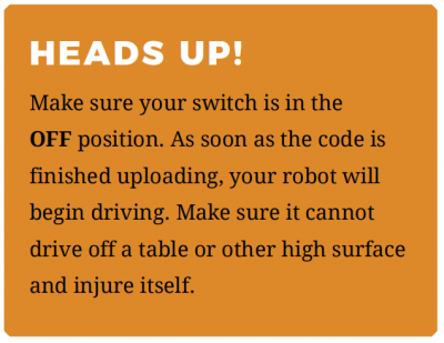
What You Will See
When the switch is turned off, the robot will sit still.
When the switch is turned on, the robot will drive forward until it senses an object.
When it senses an object in its path, it will reverse and then turn to avoid the obstacle.
Circuit 25: Object Following Robot
About this circuit:
In this circuit, you’ll control two motors and build your own object following robot! The robot that you will build uses a simple ultrasonic sensor to follow an object wherever it moves.
What You Need:
- Gear Motor x 2
- TB6612FNG Motor Driver x 1
- Slide switch x 1
- ultrasonic sensor x 1
- Jumper wires x 25
Hookup Guide:
Check out the circuit diagram and hookup table below to see how everything is connected.

Upload Code:
- 1)Connect the REV4 Board to a USB port on your computer.
- 2)Open the program in the code folder- Circuit 25, or directly copy and paste the code below on the Ardunio IDE.
- 3)Select UPLOAD to program the sketch on the REV4 Board.
int AIN1=2;
int AIN2=3;
int STBY=4;
int BIN1=5;
int BIN2=6;
int PWMA=10;// enable pin 1
int PWMB=11;// enable pin 2
int pinTrip = 8;  //define ultrasonic ting pin to D12
int pinEcho = 9;   //define ultrasonic echo pin to D13
int Fspeed;
int Lspeed;
int Rspeed;
void setup()
 {
  Serial.begin(9600);
  int i;
  for (i=2;i<=6;i++) // Ardunio motor driver module
  pinMode(i,OUTPUT); // set digital pins 2,3,4,5,6 as output
  pinMode(10,OUTPUT);// set digital pins 10, 11 as output
  pinMode(11,OUTPUT);
  pinMode(pinTrip,OUTPUT);
  pinMode(pinEcho,INPUT);

 }
 void ask_pin_F()   // measure the front distance
    {
      digitalWrite(pinTrip, LOW);   //  make ultrasonic emit LOW voltage 2μs
      delayMicroseconds(2);
      digitalWrite(pinTrip, HIGH);  // make ultrasonic emit HIGH voltage 10μs,here at least 10μs
      delayMicroseconds(10);
      digitalWrite(pinTrip, LOW);    // make ultrasonic emit LOW voltage
      float Fdistance = pulseIn(pinEcho, HIGH);  // read the time difference
      Fdistance= Fdistance/5.8/10;       // turn time into distance (unit:cm)
      Fspeed = Fdistance;              // read distance into Fspeedd(front speed)
      Serial.print("Fspeed = ");
      Serial.print(Fspeed );
      Serial.println("  cm");
    }
void loop()
    {
      ask_pin_F();            // read the front distance
     if(Fspeed >0&&Fspeed <= 15)         //if front distance is less than 10cm
     {
      back();
      }
      if(Fspeed >15&&Fspeed <= 20)         //if front distance is less than 10cm
     {
      stop();
      }
      if(Fspeed >20&&Fspeed <= 40)         //if front distance is less than 10cm
     {
      front();
      }
     if(Fspeed >40)         //if front distance is less than 10cm
     {
      stop();
      }
    }
void front() {
    digitalWrite(STBY,HIGH);
    digitalWrite(AIN1,HIGH);
    digitalWrite(AIN2,LOW);
    analogWrite(PWMA,200);
    digitalWrite(BIN1,HIGH);
    digitalWrite(BIN2,LOW);
    analogWrite(PWMB,200);
}

void back() {
    digitalWrite(STBY,HIGH);
    digitalWrite(AIN1,LOW);
    digitalWrite(AIN2,HIGH);
    analogWrite(PWMA,200);
    digitalWrite(BIN1,LOW);
    digitalWrite(BIN2,HIGH);
    analogWrite(PWMB,200);
}

void stop() {
  digitalWrite(STBY,LOW);
}

void left() {

    digitalWrite(STBY,HIGH);
    digitalWrite(AIN1,HIGH);
    digitalWrite(AIN2,LOW);
    analogWrite(PWMA,200);
    digitalWrite(BIN1,LOW);
    digitalWrite(BIN2,HIGH);
    analogWrite(PWMB,200);
}

void right() {
    digitalWrite(STBY,HIGH);
    digitalWrite(AIN1,LOW);
    digitalWrite(AIN2,HIGH);
    analogWrite(PWMA,200);
    digitalWrite(BIN1,HIGH);
    digitalWrite(BIN2,LOW);
    analogWrite(PWMB,200);
}
What You Will See
When the switch is turned off, the robot will sit still.
When the switch is turned on, the robot will drive forward until it senses an object.
When it senses an object in its path, it will follow an object ahead to move.
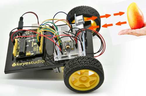
GET ALL RESOURCES FOR ROBOT PROJECTS
*Download library:
https://fs.keyestudio.com/KS0436
*Adruino software download:
https://www.arduino.cc/en/Main/OldSoftwareReleases#1.5.x
About keyestudio
Located in Shenzhen, the Silicon Valley of China, KEYES DIY ROBOT co.,LTD is a thriving technology company dedicated to open-source hardware research and development, production and marketing.
Keyestudio is a best-selling brand owned by KEYES Corporation, our product lines range from Arduino boards, shields, sensor modules, Raspberry Pi, micro:bit extension boards and smart car to complete starter kits designed for customers of any level to learn Arduino knowledge.
All of our products comply with international quality standards and are greatly appreciated in a variety of different markets throughout the world.
Welcome check more contents from our official website:
http://www.keyestudio.com
For more details of our products, you can check it from the links below.
- WIKI Website: https://wiki.keyestudio.com
- US Amazon storefront: http://www.amazon.com/shops/A26TCVWBQE4D9T
- CA Amazon storefront: http://www.amazon.ca/shops/A26TCVWBQE4D9T
- UK Amazon storefront: http://www.amazon.co.uk/shops/A39F7KX4U3W9JH
- DE Amazon storefront: http://www.amazon.de/shops/A39F7KX4U3W9JH
- FR Amazon storefront: http://www.amazon.de/shops/A39F7KX4U3W9JH
- ES Amazon storefront: http://www.amazon.de/shops/A39F7KX4U3W9JH
- IT Amazon storefront: http://www.amazon.de/shops/A39F7KX4U3W9JH
- US Amazon storefront: http://www.amazon.com/shops/APU90DTITU5DG
- CA Amazon storefront: http://www.amazon.ca/shops/APU90DTITU5DG
- JP Amazon storefront: http://www.amazon.jp/shops/AE9VWCCXQIC6J
Customer Service
As a continuous and fast growing technology company, we keep striving our best to offer you excellent products and quality service as to meet your expectation.
We look forward to hearing from you and any of your critical comment or suggestion would be much valuable to us.
You can reach out to us by simply drop a line at: Fennie@keyestudio.com
Thank you in advance.
Buy From
