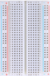
CZ0487 Duinotech Beginner Starter Kit for micro bit(Excluding the Mainboard)
Note: the micro:bit has beed updated to V2.0 version; therefore, you can get more details for CZ0487 V2.0 basic kit in the following link:
https://fs.keyestudio.com/CZ0487
Kit Description
keyestudio Beginner Starter Kit for micro:bit is designed for those who love to learn programming. micro: bit is a microcontroller of ARM structure designed by BBC. It is only half size of a credit card, and onboard comes with Bluetooth, accelerometer, electronic compass, three buttons, 5 x 5 LED dot matrix, mainly used for teens programming education.
We specially make this starter kit for you to conveniently learn micro:bit, where includes common used resistors, LEDs, sensors, LED segment display and more, so you can directly start doing the experiments without purchasing other components.The kit also provides you with micro:bit study courses, wiring method and testing code, helping you quickly grasp the programming knowledge. Believing that our Beginner Starter Kit for micro bit can lead you to a wonderful electronic world.
Note: we adopt V1.5 micro:bit in the whole tutorial, but our tutorial is also compatible with the latest version micro:bit. When doing experiment with latest micro:bit, you need to transfer code into Makecode online editor first, save code again then download it to micro:bit.
Note:
Micro:bit works at 3.3V. Shield just leads out ports of micro:bit without adding other circuit. When connected sernsors or modules, shield only adds components compatible with 3.3v.
Kit List
micro:bit Driver Installation
How to install the driver for micro:bit development board?
a. First, connect micro:bit development board to computer using a USB cable, then double-click mbedWinSerial_16466
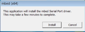
Click “Install”.
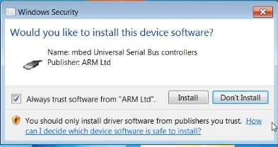
b. Tick the option, then continue to click “Install” to install the driver.
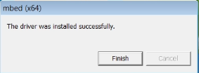
c. Click “Finish”, installation finished.
d. On the computer bottom right corner, the below icon display means that the related driver software is installed automatically.

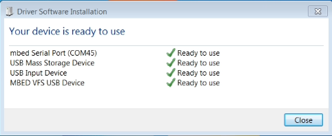
e. Driver software installation finished. Shown below.
f. Right click “Computer” —>“Properties”—> “Device manager”, you can check the below Ports.

micro:bit Using Method
Step 1: Connect It
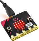
Connect the micro:bit to your computer via a micro USB cable. Your micro:bit will show up on your computer as a drive called 'MICROBIT'.
Step 2: Program It
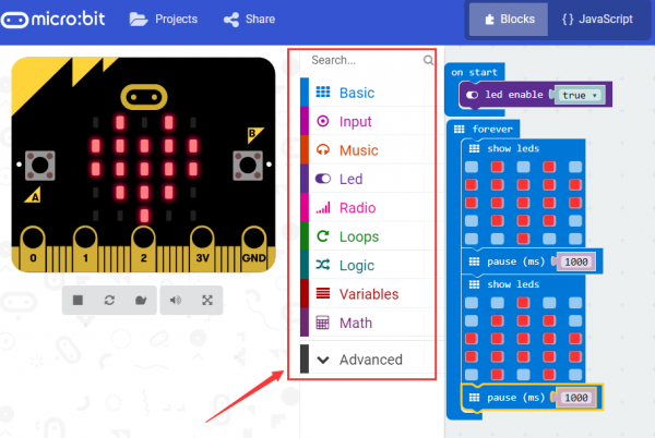
Using micro bit MakeCode Block editor https://makecode.microbit.org/, write your first micro:bit code. You can drag and drop some example blocks and try your program on the Simulator in the Javascript Blocks Editor, like in the image below.
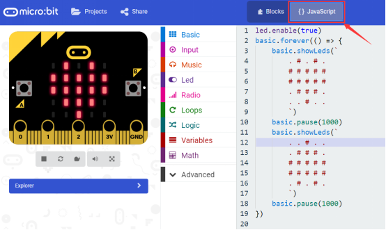
Click the JavaScript, you can see the corresponding program code. Shown as below figure.
Step 3: Download It
Click the Download button in the editor. This will download a 'hex' file, which is a compact format of your program that your micro:bit can read.
Here you can name the project as LED1, then click “Save”. Shown below.

Once the hex file has downloaded, copy it to your micro:bit just like copying a file to a USB drive. On Windows find the microbit-LED1 file, you can right click and choose "Send To→MICROBIT."


Step 4: Play It
The micro:bit will pause and the yellow 5*5 LED on the back of the micro:bit will display the images while your code is programmed.

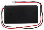
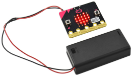
You can power it using USB cable or battery. The battery holder need to connect two 1.5V AA batteries. Shown below.
Experimental Courses
Lesson 1: Displaying Hello World
Description
First, let’s start a pretty simple experiment that make your micro bit main board display “Hello World!” only using a micro bit main board and a USB cable. This is an entry level for you to test the communication between micro bit and PC. Here we will use a serial communication software (Arduino IDE), hope that we will lead you to a wonderful micro bit world.
Hardware Required
- Micro:bit main board *1
- USB cable *1
Testing Code
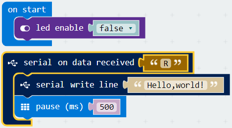
If you are not familiar to make code, don't worry. At first, you can enter this link: https://makecode.microbit.org/reference to get the reference of microbit block.
Install Arduino IDE
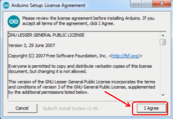
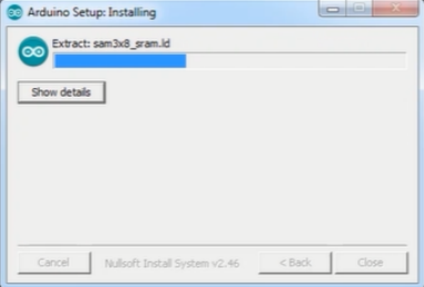
a. Double click arduino-1.5.6-r2-windows to start.
Select “I Agree”to accept license agreement.
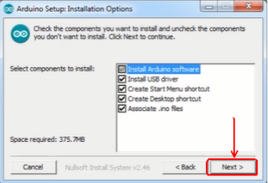
b. Select components to install and click “Next”.
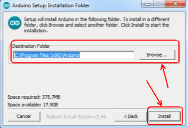
c. Click “Browse” and select another folder. Click “Install” to start the installation.
d. Finally, wait for a few minutes to finish.
Testing Result
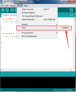
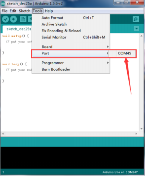
Connect the micro:bit board to computer, powered up, open Arduino IDE, set the COM port as below figure shown, then upload the testing code.
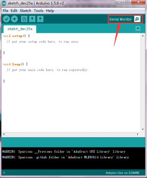
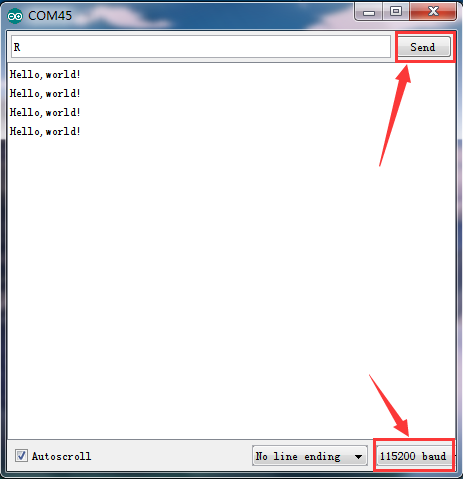
Finally, open serial monitor, select the baud rate 115200 (because the baud rate of micro:bit serial communication is 115200), enter an “R”, then click “Send”, you can see the monitor display “Hello world!”. Shown below.
Lesson 2: Blinking an LED
Description
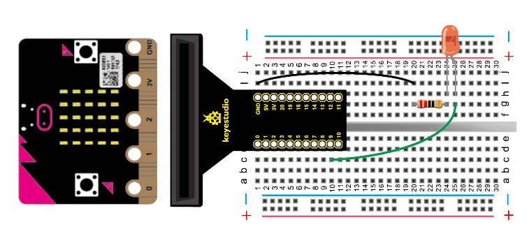
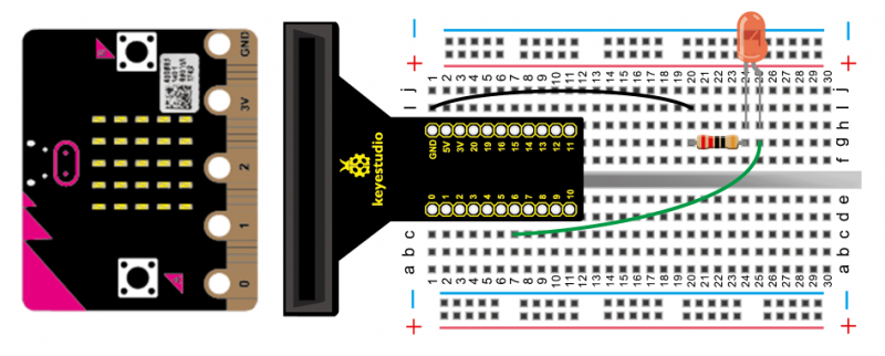
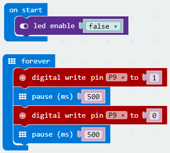
LED blinking is one of the basic experiments. In micro:bit using method, you can see the 5* 5 LED dot matrix is enabled. Here we are going to finish LED blinking experiment using an external plug LED, so at first you have to close the led enable function.
Hardware Required
- micro:bit main board *1
- keyestudio T-type adapter*1
- USB cable*1
- LED *1
- 220Ω resistor *1
- Breadboard *1
- Breadboard jumper wire * 2
Testing Code
If you are not familiar to make code, don't worry. At first, you can enter this link: https://makecode.microbit.org/reference to get the reference of microbit block.
Testing Result
Powered up, done uploading the code to board, you can see the external LED light connected on IO port is blinking, with an interval about 0.5 second.
Lesson 3: Simulating Advertising Light
Description
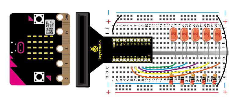
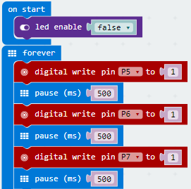
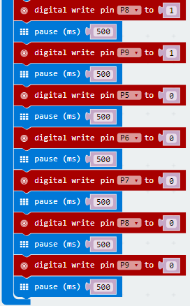
In daily life, you may often see some advertising boards composed of various LED lights. Different LED lights on the advertising board can form an amazing lighting effect. In this lesson, we will use LED light program to simulate the advertising light, brightening and dimming one by one.
Hardware Required
- micro: bit main board *1
- keyestudio T-type adapter *1
- USB cable *1
- LED *5
- 220Ω resistor *5
- Breadboard *1
- Breadboard jumper wire* 7
Testing Code
If you are not familiar to make code, don't worry. At first, you can enter this link: https://makecode.microbit.org/reference to get the reference of microbit block.
Testing Result
Powered up and done uploading the code, you can see the external LED lights connected on IO port are brightening, and then dimming one by one circularly.
Lesson 4: Button-controlled LED
Description
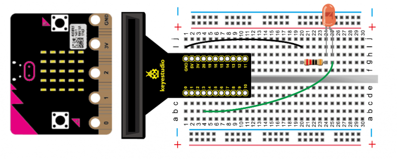
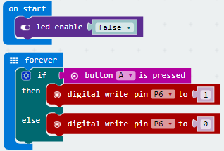
Micro:bit has three built-in buttons, two for user buttons (labelled A and B), one for reset button. This time, we are going to use a user button on the micro:bit to control external LED on and off.
Hardware Required
- micro: bit main board *1
- keyestudio T-type adapter *1
- USB cable *1
- LED *1
- 220Ω resistor *1
- Breadboard *1
- Breadboard jumper wire * 2
Testing Code
If you are not familiar to make code, don't worry. At first, you can enter this link: https://makecode.microbit.org/reference to get the reference of microbit block.
Testing Result
Powered up, done uploading the code to board, when pressing down the button A on the micro:bit, LED on; if not, LED off.
Lesson 5: Making a Responder
Description
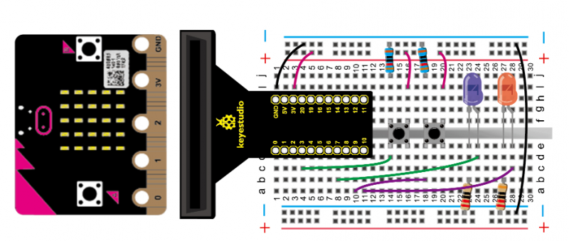
We have use micro:bit built-in button to control LED light in the previous experiment. This time, we will use it to make a responder, really interesting. Using a built-in button on micro:bit as reset button, connecting two tactile buttons as responder button to control two external LEDs.
Hardware Required
- micro: bit main board *1
- keyestudio T-type adapter *1
- USB cable *1
- LED *2
- Tactile button *2
- 220Ω resistor *2
- 10KΩ resistor *2
- Breadboard *1
- Breadboard jumper wire * 9
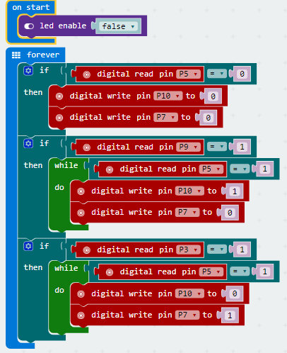
Testing Code
If you are not familiar to make code, don't worry. At first, you can enter this link: https://makecode.microbit.org/reference to get the reference of microbit block.
Testing Result
Powered up and done uploading the code, a simple responder is finished. You can judge who
answer first successfully according to the displayed color of LED. Press down the button A
on micro:bit used as reset button, two LED lights off.
Lesson 6: Breathing an LED
Description
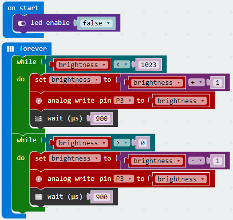
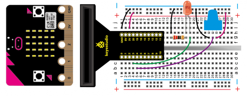
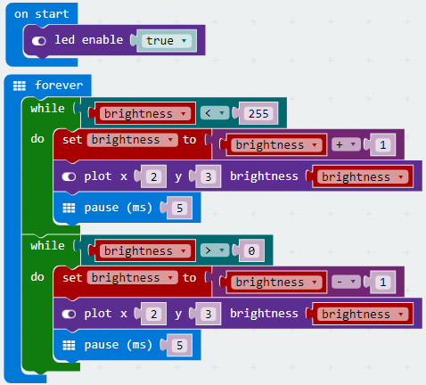
You may have mastered LED on and off controlling based on the above projects, so this time learn to control LED brightness in the code. We are going to control LED on and off gradually, just like breathing simulation. So need to control 25 programmable LEDs on micro:bit and external LED to achieve breathing light effect. Note that external LED must be connected to analog port.
Hardware Required
- micro: bit main board *1
- keyestudio T-type adapter *1
- USB cable *1
- LED *1
- 220Ω resistor * 1
- Breadboard *1
- Breadboard jumper wire *2
Testing Code
If you are not familiar to make code, don't worry. At first, you can enter this link: https://makecode.microbit.org/reference to get the reference of microbit block.
5*5 LED matrix:
Testing Result
Powered up, done uploading the code, LED is gradually dimming, and then brightening alternatively, looking like breathing.
Lesson 7: Controlling LED Brightness
Description
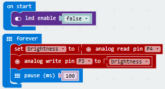
In previous lesson, we have directly control the LED brightness in the code. In this lesson, you will learn how to use a potentiometer to control the brightness of an LED. Note that external LED and potentiometer must be connected to analog port.
Hardware Required
- micro: bit main board *1
- keyestudio T-type adapter *1
- USB cable *1
- LED *1
- 220Ω resistor * 1
- Potentiometer *1
- Breadboard *1
- Breadboard jumper wire *7
Testing Code
If you are not familiar to make code, don't worry. At first, you can enter this link: https://makecode.microbit.org/reference to get the reference of microbit block.
Testing Result
Done wiring and uploading the code, you can adjust the brightness of LED by rotating the knob on the potentiometer.
Lesson 8: RGB LED
Description
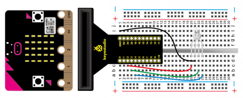
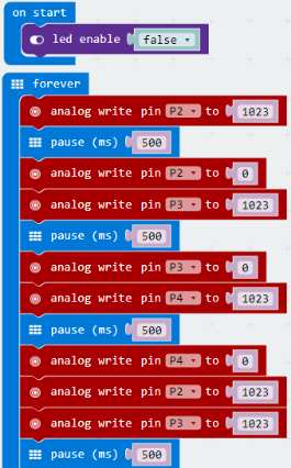
RGB color model is an additive color model in which red, green and blue light are added together in various way to reproduce a broad array colors. The name of the model RGB comes from the initials of the three additive primary colors, red, green, and blue. In this lesson, we will use a RGB light to achieve full-color mixing effect, through controlling the voltage input of R、G、B pins to adjust the intensity of three primary colors (red/green/blue).
Hardware Required
- micro: bit main board *1
- keyestudio T-type adapter *1
- USB cable *1
- RGB*1
- Breadboard *1
- Breadboard jumper wire * 4
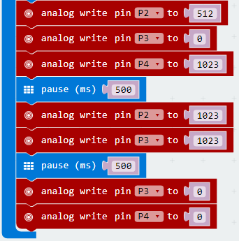
Testing Code
If you are not familiar to make code, don't worry. At first, you can enter this link: https://makecode.microbit.org/reference to get the reference of microbit block.
Testing Result
Done wiring and powered up, downloading the code to micro: bit, you can see the RGB LED will continue to emit red light for 1S, green light for 1S, blue light for 1S, yellow light for 1S, purple light for 1S, white light for 1S, circularly.
Lesson 9: Photosensitive Light
Description
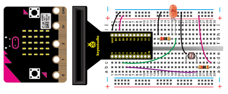
This lesson, let’s start a rather simple photocell experiment. Photocell is a component that can change its resistance according to the light intensity. In this experiment, you can learn from the LED brightness controlled by potentiometer, just replace the potentiometer with photocell to achieve the effect that the brightness of LED will be changed once light intensity is different.
Hardware Required
- micro: bit main board *1
- keyestudio T-type adapter *1
- USB cable *1
- LED *1
- 220Ω resistor * 1
- 5MM photocell *1
- 10Ω resistor * 1
- Breadboard *1
- Breadboard jumper wire * 7
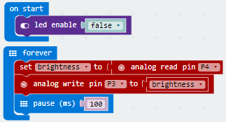
Testing Code
If you are not familiar to make code, don't worry. At first, you can enter this link: https://makecode.microbit.org/reference to get the reference of microbit block.
Testing Result
Done downloading the code into micro:bit, you can see that the brighter the photocell senses, the darker the LED; the darker the photocell senses, the brighter the LED.
Lesson 10: Active Buzzer
Description
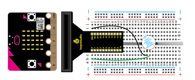
There are two kinds of buzzer, active buzzer and passive buzzer. In this lesson, we will use micro:bit to drive an active buzzer. The active buzzer inside has a simple oscillator circuit which can convert constant direct current into a certain frequency pulse signal. Once active buzzer receives a high level, it will produce an audible beep.
Hardware Required
- micro: bit main board *1
- keyestudio T-type adapter *1
- USB cable *1
- Active buzzer *1
- Breadboard *1
- Breadboard jumper wire * 2
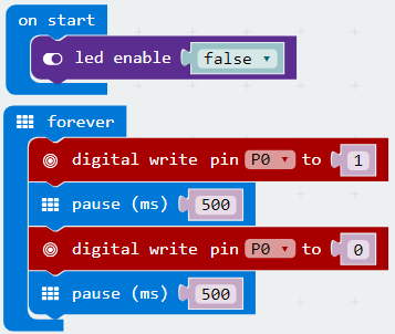
Testing Code
If you are not familiar to make code, don't worry. At first, you can enter this link: https://makecode.microbit.org/reference to get the reference of microbit block.
Testing Result
Finally, you can hear the active buzzer beep for 0.5 seconds, then stop and beep for 0.5 seconds circularly.
Lesson 11: Passive Buzzer
Description
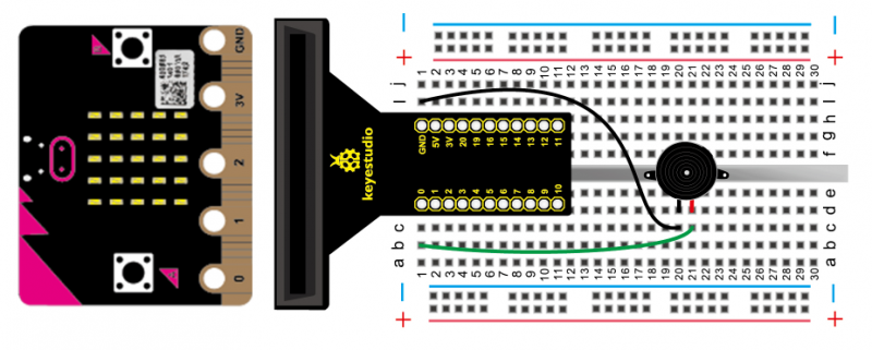
You have learned about the active buzzer. So this lesson will use a passive buzzer to play a song. It comes with a fun application, give it a try! Since the passive buzzer has no oscillator inside, DC signal can’t make it beep, so need to use square-wave to drive it.
Hardware Required
- micro: bit main board *1
- keyestudio T-type adapter *1
- USB cable *1
- Passive buzzer *1
- Breadboard *1
- Breadboard jumper wire * 2
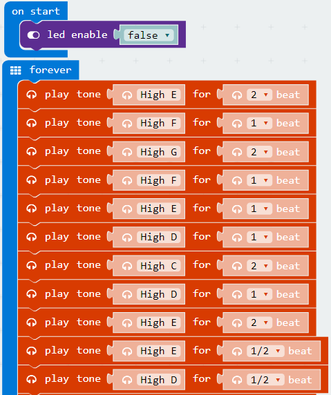
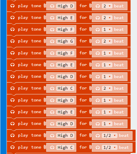
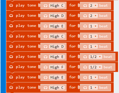
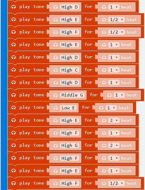
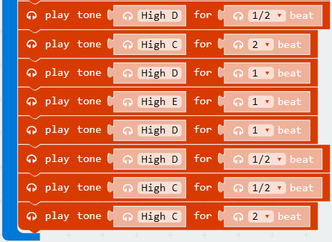
Testing Code
If you are not familiar to make code, don't worry. At first, you can enter this link: https://makecode.microbit.org/reference to get the reference of microbit block.
Testing Result
Downloading the code into micro: bit, you can hear the buzzer playing the song of 《Ode To Joy》. Enjoy your time!
Lesson 12: Driving Servo Motor
Description
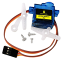
Servo motor is a position control rotary actuator. It mainly consists of housing, circuit board, core-less motor, gear and position sensor. Servomotor comes with many specifications. But all of them have three connection wires, distinguished by brown, red and orange (different brand may have different color). Brown one is for GND, red one for power positive, orange one for signal line.
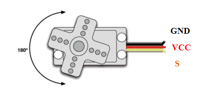
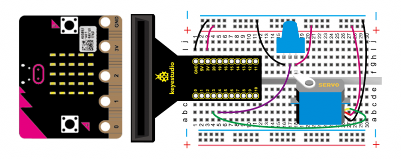
In this experiment, we will use a potentiometer to adjust the turning angle of servo motor. When rotating the knob on the potentiometer, servo motor will turn.
Hardware Required
- micro: bit main board *1
- keyestudio T-type adapter *1
- USB cable *1
- 9G servo motor *1
- Potentiometer *1
- Breadboard *1
- Breadboard jumper wire * 8
Wiring Diagram
Testing Code
If you are not familiar to make code, don't worry. At first, you can enter this link: https://makecode.microbit.org/reference to get the reference of microbit block.
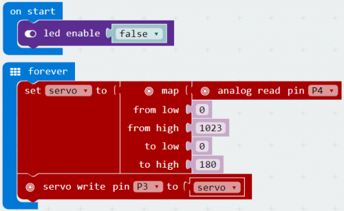
Testing Result
Done wiring and downloading the code into micro:bit, you can rotate the knob on the top of potentiometer to adjust the turning angle of servo motor.
Lesson 13: Flame Alarm
Description
Flame sensor (Infrared receiving triode) is specially used on robots to find the fire source. This sensor is of high sensitivity to flame. Flame sensor is made based on the principle that infrared ray is highly sensitive to flame. It has an infrared receiving tube to detect fire, and then converts the flame brightness into fluctuating level signal.
In this experiment, we are going to control the buzzer sound through inputting the fluctuating level signal into micro:bit board.
Hardware Required
- micro: bit main board *1
- keyestudio T-type adapter *1
- USB cable *1
- Flame sensor *1
- Active buzzer *1
- 10KΩ resistor *1
- Breadboard *1
- Breadboard jumper wire * 7
Wiring Diagram
Connection for flame sensor:
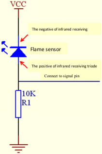
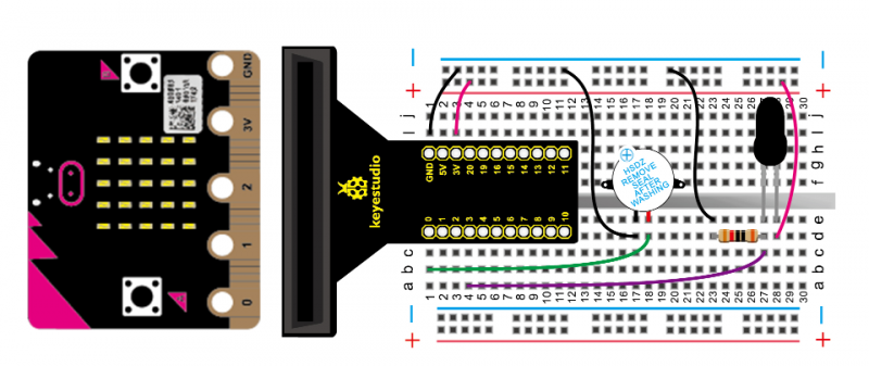
Testing Code
If you are not familiar to make code, don't worry. At first, you can enter this link: https://makecode.microbit.org/reference to get the reference of microbit block.
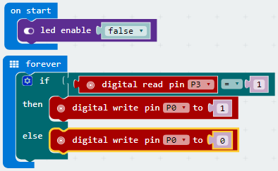
Testing Result
If flame sensor detects the flame nearby, the active buzzer beeps; or else, it will not sound.
Lesson 14: 1-digit LED Display
Description
LED segment display is a semiconductor light-emitting device. Its basic unit is a light emitting diode (LED). This lesson, we will use 1-digit 7-segment LED display.
Please refer to the below schematic diagram.
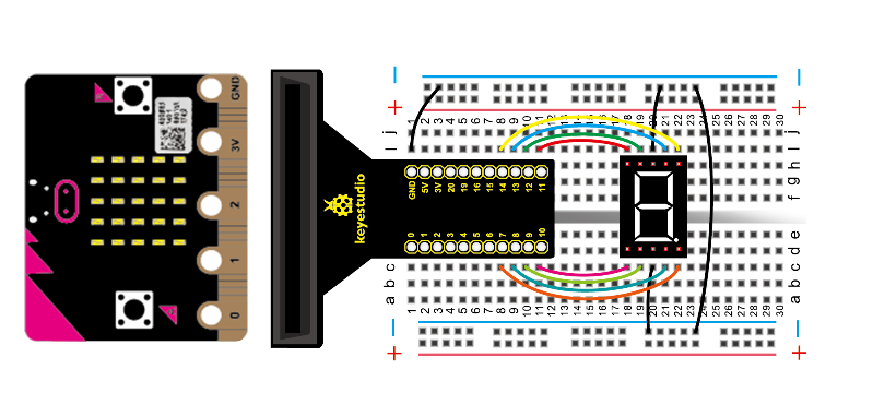
We can control the display of LED segment display through controlling the high/low level of its interface. Interface connection shown in the below table. This time, we are going to use LED display to show the number from 0 to 9.
| LED display | Micro:bit main board |
|---|---|
| a | P13 |
| b | P14 |
| c | P8 |
| d | P9 |
| e | P10 |
| f | P12 |
| h | P7 |
Hardware Required
- micro: bit main board *1
- keyestudio T-type adapter *1
- USB cable *1
- 1-digit LED display *1
- Breadboard *1
- Breadboard jumper wire * 12
Testing Code
If you are not familiar to make code, don't worry. At first, you can enter this link: https://makecode.microbit.org/reference to get the reference of microbit block.
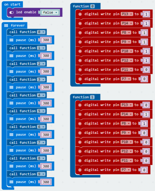
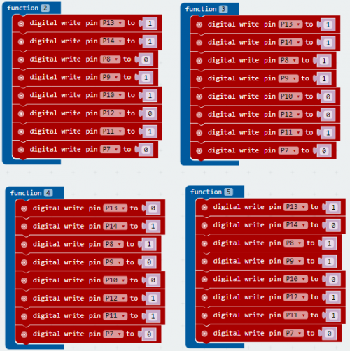
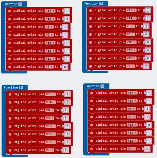
Testing Result
Done wiring and downloading the code into micro:bit, you can see the LED segment display showing the numbers from 0 to 9 circularly.

Lesson 15: Magical Light Cup
Description
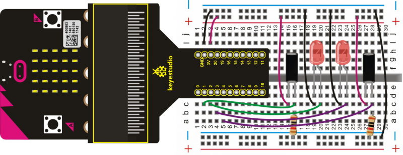
When one end of tilt switch is lower than the horizontal position, it performs a turn-on operation; while another end is lower than the horizontal position, tilt switch turns off.The experiment adopts the principle of using analog value to regulate light brightness. So the brightness of two LEDs in the experiment will make a change. The ball tilt switch provides digital signal to trigger analog value regulation, after programming, you can see the magical light effect of these two LEDs.
Hardware Required
- micro: bit main board *1
- keyestudio T-type adapter *1
- USB cable *1
- Ball tilt switch *2
- LED *2
- 10KΩ resistor *2
- Breadboard *1
- Breadboard jumper wire * 11
Testing Code
If you are not familiar to make code, don't worry. At first, you can enter this link: https://makecode.microbit.org/reference to get the reference of microbit block.
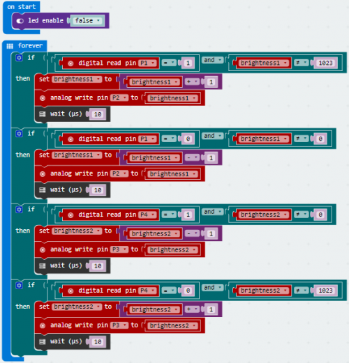
Testing Result
Wiring and downloading the code into micro:bit, tilt the two switches to common one side at the same time, you can see that one LED dims gradually, while another one becomes brighter gradually. Finally, one LED off, while the other becomes the brightest.
Lesson 16: Micro:bit Analog Read
Description
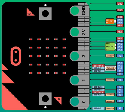
In this experiment, we will use a potentiometer to adjust the analog quantity of P2 (refer to the below pin guide). When rotating the potentiometer, analog quantity makes a change and is displayed on the serial monitor.
Note that it needs to use a serial communication software, Arduino IDE.
Hardware Required
- micro: bit main board *1
- keyestudio T-type adapter *1
- USB cable *1
- Potentiometer *1
- Breadboard *1
- Breadboard jumper wire * 3
Testing Code
If you are not familiar to make code, don't worry. At first, you can enter this link: https://makecode.microbit.org/reference to get the reference of microbit block.
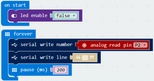
Testing Result
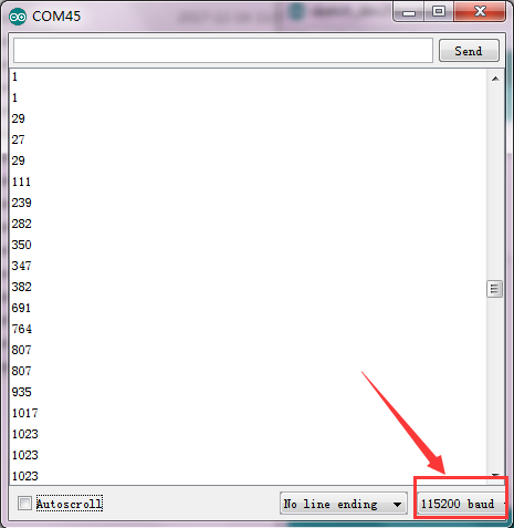
Wiring as above diagram, open Arduino IDE, set the COM port shown below, and download the code into micro:bit board. Then, open serial monitor, set the baud rate as 115200 (because micro:bit serial communication baud rate is 115200).
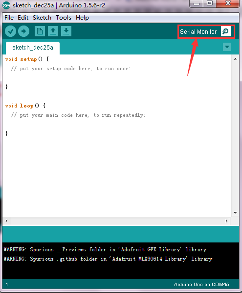
Finally, you can see the monitor display the value. Rotating the knob on the potentiometer, the value varies from 1 to 1023.
Lesson 17: Thermistor Sensor
Description
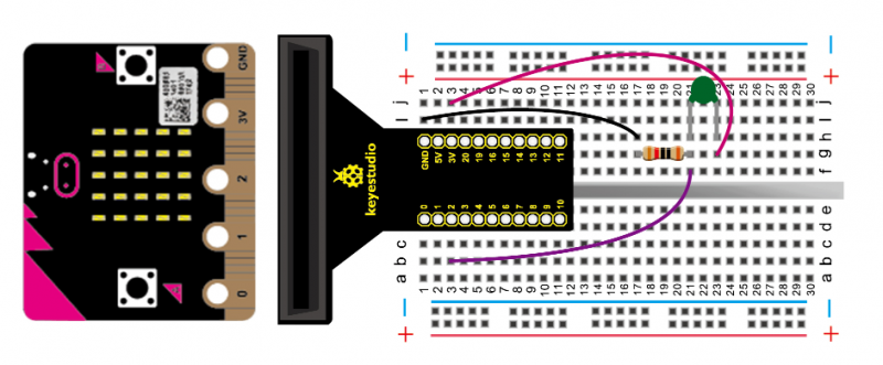
Thermistor sensor can sense the temperature change of surroundings in real time, also will vary from temperature variation. In the circuit, it will convert the temperature variation into voltage change, and input the voltage to P2 of micro:bit board. Finally, display the analog quantity of P2 on the serial monitor.
Note that you need to use a serial communication software, namely, Arduino IDE.
Hardware Required
- micro: bit main board *1
- keyestudio T-type adapter *1
- USB cable *1
- Thermistor sensor (green)*1
- 10KΩ resistor *1
- Breadboard *1
- Breadboard jumper wire * 3
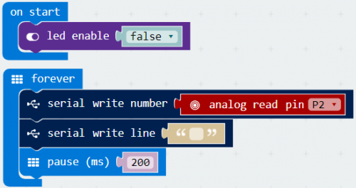
Testing Code
If you are not familiar to make code, don't worry. At first, you can enter this link: https://makecode.microbit.org/reference to get the reference of microbit block.
Testing Result
Wiring as above diagram, open Arduino IDE, set well the COM port, and download the code into micro:bit. Then, open serial monitor, set the baud rate as 115200 (because micro:bit serial communication baud rate is 115200).
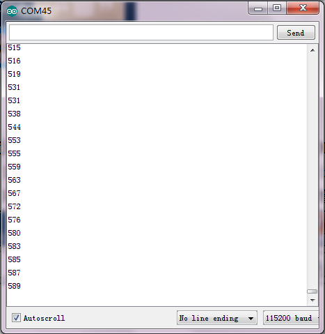
Finally, you can see the value is displayed on serial monitor. When thermistor temperature rises, the resistance will decrease, analog value increases.
For example, when you breathe on the thermistor, its temperature will rise, so analog value increases. Shown as the figure below.
Lesson 18: LM35 Temperature Sensor
Description
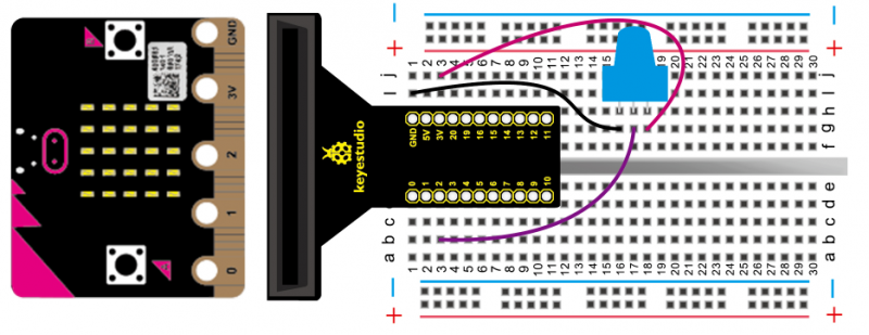
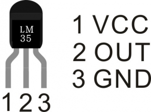
LM35 is a common use temperature sensor. Using a LM35 and an analog port can detect the current temperature. The output voltage has linear relationship with the Celsius scale. For example, when temperature is 0 ℃, it outputs 0V; if increasing 1 ℃, the output voltage will increase 10 mv. Input its output voltage into P2 on micro:bit main board, after formula computing, display the temperature value of current surroundings on the serial monitor. In this way, we will use a serial communication software, Arduino IDE.
Notice the wiring direction of LM35, or else it will damage the LM35 sensor if reversed.
Hardware Required
- micro: bit main board *1
- keyestudio T-type adapter *1
- USB cable *1
- LM35DZ*1
- Breadboard *1
- Breadboard jumper wire * 3
Testing Code
If you are not familiar to make code, don't worry. At first, you can enter this link: https://makecode.microbit.org/reference to get the reference of microbit block.
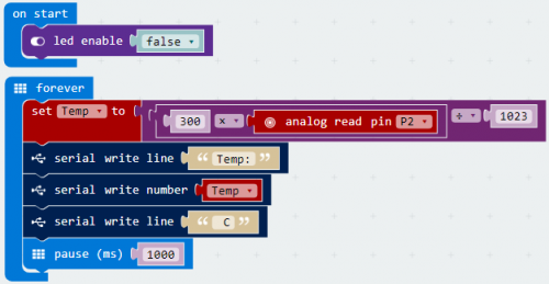
Testing Result
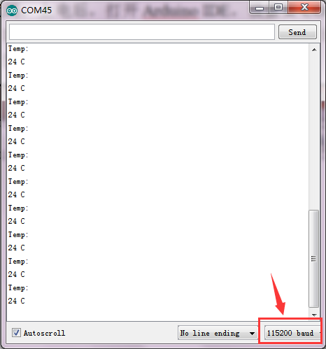
Wiring as above diagram, open Arduino IDE, set well the COM port and download the code into micro:bit. Then, open serial monitor, set the baud rate as 115200 (because micro:bit serial communication baud rate is 115200). You can see the temperature value of current surroundings on the serial monitor. Shown below.
Related Study Link
- BBC micro:bit website
- Micro:bit MakeCode Block Editor
- Meet micro:bit starter programming
- BBC micro:bit Features Guide
- BBC micro:bit Safety Warnings
- BBC micro:bit Quick Start Guide
- BBC micro:bit Pins
Documents
Driver Installation Video, Driver and code :
https://fs.keyestudio.com/CZ0487
Download ARDUINO Software:
https://www.arduino.cc/en/Main/OldSoftwareReleases#1.5.x
Resources (in Japanese):
https://1drv.ms/u/s!ArhgRvK6-RyJhXjVAedoJX3IVBmh?e=nePzQR

