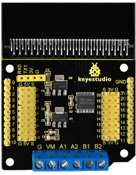
Ks0308 keyestudio Motor Drive Breakout Board for micro bit
Description
The BBC micro:bit is a powerful handheld, fully programmable, computer designed by the BBC. It was designed to encourage children to get actively involved in technical activities, like coding and electronics.
It features a 5x5 LED Matrix, two integrated push buttons, a compass, Accelerometer, and Bluetooth.
It supports the PXT graphical programming interface developed by Microsoft and can be used under Windows, MacOS, IOS, Android and many other operating systems without downloading the additional compiler.
Looking to do more with your BBC micro:bit? Unlock its potential with this motor drive breakout board for the BBC micro:bit!
The motor drive breakout board integrates TB6612FNG chip. Its per channel can output up to 1.2 A continuous drive current, with peak current up to 2A/3.2A.
There are 4 motor control modes: Forward/Reverse /Brake /Stop. And PWM supporting frequency is up to 100 kHz.
The BBC micro:bit pins are broken out to 3PIN headers. These provide an easy way of connecting circuits using 3PIN jumper wires.
At the same time, a 3.3V and 5V voltage-regulator chip is integrated on the breakout board, breaking out 3.3V and 5V power output interfaces.
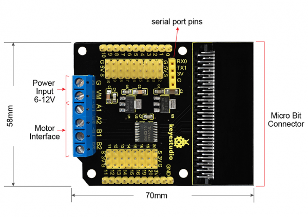
The board also comes with serial port communication pins.
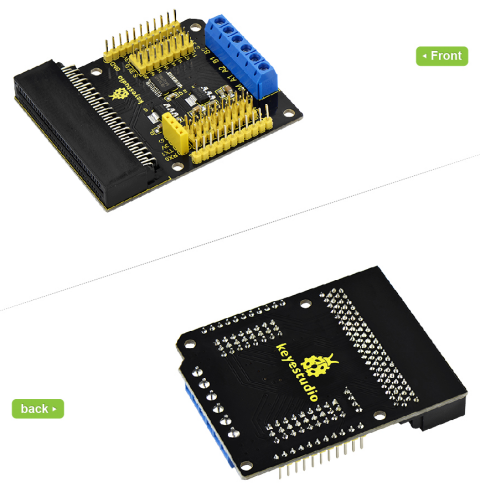
Note: we adopt V1.5 micro:bit in the whole tutorial, but our tutorial is also compatible with the latest version micro:bit.
When doing experiment with latest micro:bit, you need to transfer code into Makecode online editor first, save code again then download it to micro:bit.
Features
- Four motor control modes: Forward/Reverse /Brake /Stop.
- Access to 3Pin headers connection
- Integrated with 3.3V and 5V voltage-regulator chip
- Comes with serial port communication pins
Parameters
- Input Voltage:DC 6-12V
- Drive Partial Working Current:≤1.2A
- Size:70mm*58mm
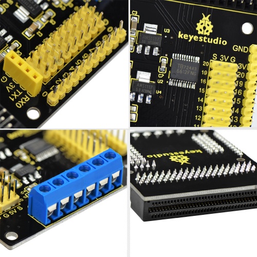
Details Display
Wiring Diagram
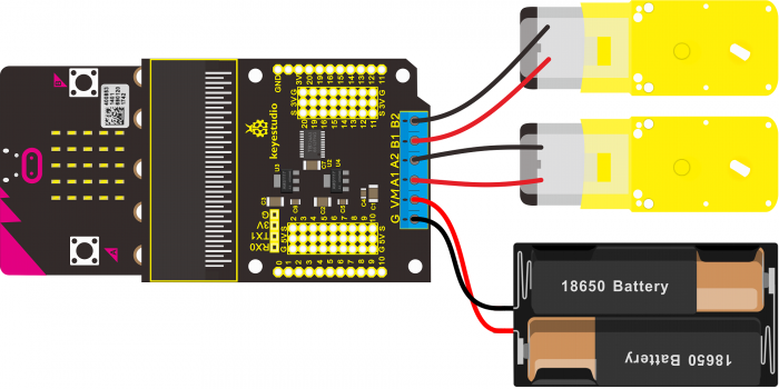
Here show you the wiring diagram below, connect the microbit and motor to our motor drive breakout board, you can observe the motor rotation.
Connect the two motors to terminal block A1,A2,B1,B2; GND to battery negative end, VM terminal to battery positive end.
Test Code
You can directly copy the below code to microbit or try to edit it on micro bit Blocks Editor
If you can get the code edit successfully, you will be crazy with delight.
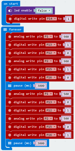
The code explanation as below:
Motor1 forward:
P13 - HIGH
P12 - LOW
Speed PWM: P1

Motor2 forward:
P15 - HIGH
P16 - LOW
Speed PWM: P2

Motor1 Backward:
P13 - LOW
P12 - HIGH
Speed PWM: P1

Motor2 Backward:
P15 - LOW
P16 - HIGH
Speed PWM: P2
Test Result
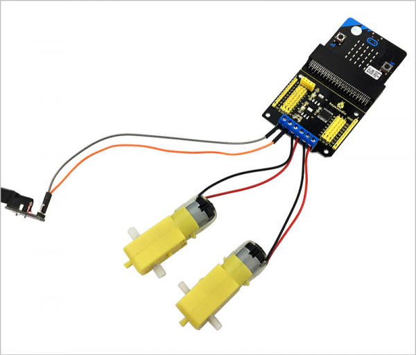
Wiring as the above diagram, done powering up and uploading the code, two motors first turn forward for 3 seconds, then reverse for 3 seconds, circularly.
Go Further
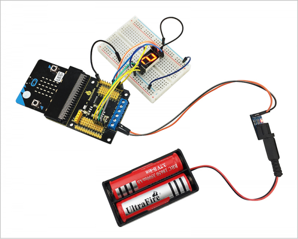
You can use the motor drive breakout board to control the 1-digit LED segment display. Design the circuit with your micro:bit main board and breadboard and more.
Resources
- Click here to download the datasheet and code
- BBC micro:bit website
- Micro:bit MakeCode Block Editor
- Meet micro:bit starter programming
- BBC micro:bit Features Guide
- BBC micro:bit Safety Warnings
- BBC micro:bit Quick Start Guide
- BBC micro:bit Pins
