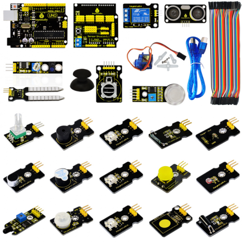
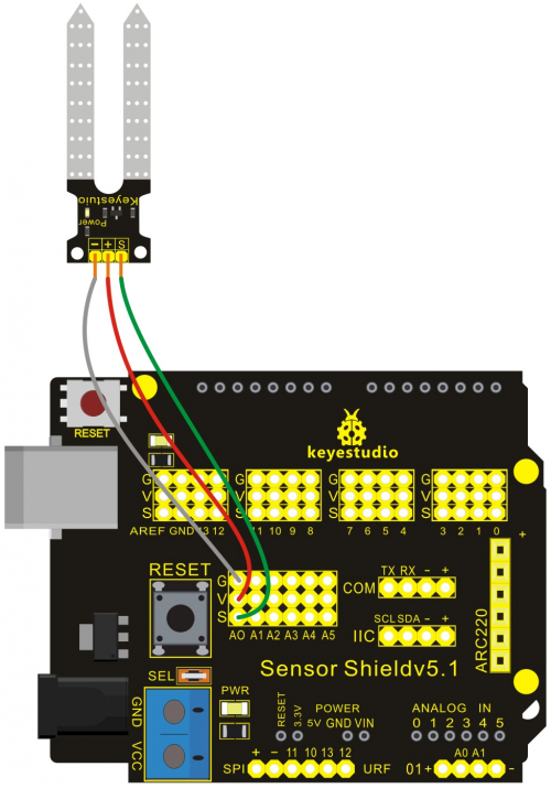
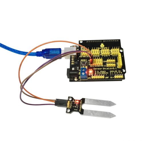
Ks0086 ARDUBLOCK Graphical Programming Starter Kit
ARDUBLOCK Graphical Programming Starter Kit
1. Introduction
Ardublock zero-based programming kit is a new graphical programming study kit which is based on Arduino enthusiasts and developed by keyestudio. It greatly lowers the difficulty in program learning for enthusiasts. All computer language and professional statements of a program can be simplified into blocks. Compiling is as easy as block building. Interactive with Arduino development board, they can achieve exciting works.
The open source feature of Arduino makes it extremely popular. You can find a many learning communities on the Internet. Ardublock is a graphical programming environment, just like blocks building, which greatly lowers the learning difficulty for starters. As long as you love it, everyone can play with Arduino without professional knowledge or relevant background. As for parents who stress on the education of next generation, this will be one of your best way to interact with your children.
2. Kit Contents
Project 1  LED Blinking
Project 2  PWM Regulating Light Brightness
Project 3  Flowing Light
Project 4  Button-controlled LED
Project 5  Passive Buzzer Sound Production
Project 6  Active Buzzer Sound Production
Project 7  Reading-out Analog Value
Project 8  Light-controlled Sound
Project 9  Sound-controlled Light
Project 10  Servo Motor Control
Project 11  Ultrasonic Distance Measurement
Project 12  PS2 Joystick Module
Project 13  LM35 Temperature Sensor
Project 14  5V Relay Module
Project 15  Tilting Switch Module
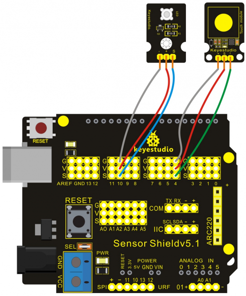
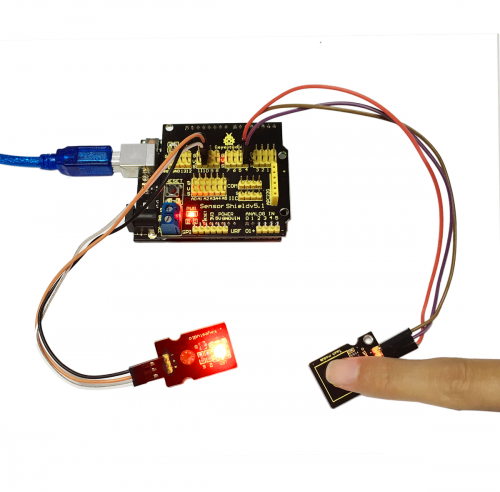
Project 16  Capacitive Touch Module Control LED
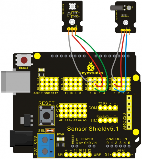
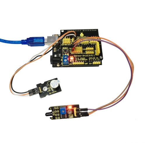
Project 17  Flame Alarm Module
Project 18  Reed Switch Module
Project 19  Human Body IR Pyroelectricity
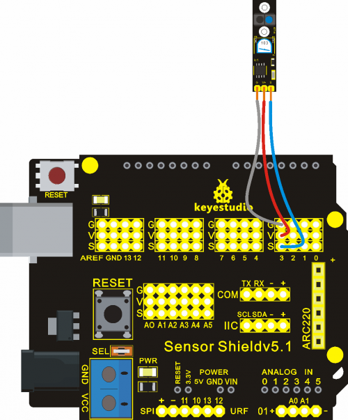
Project 20  Line Tracking Sensor
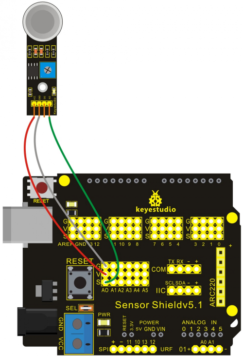
Project 21  MQ-2 Combustible Gas and Smoke Sensor
Project 22  Soil Module
3. Application of Arduino
Introduction
What’s Arduino? Arduino is an open-source hardware project platform. This platform includes a circuit board with simple I/O function and program development environment software. It can be used to develop interactive products. For example, it can read signals of multiple switches and sensors, and control light, servo motor and other various physical devices. It’s widely applied in robot field.
4. Arduino installation and program upload
First, download Arduino development software, click below hyperlink:
https://www.arduino.cc/en/Main/OldSoftwareReleases#1.5.x
Downloaded file is an arduino-1.5.6-r2-windows.zip compressed folder, and unzip it to your hard drive.
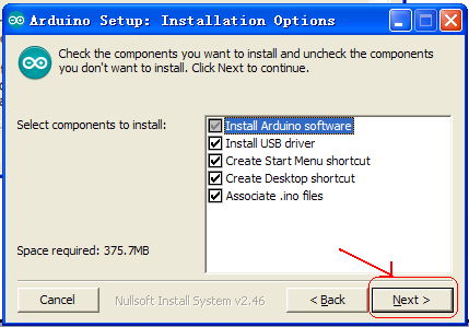
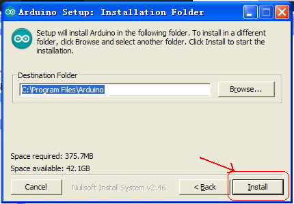
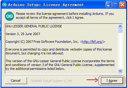
Double click Arduino-1.5.6 .exe. and select “I agree”.
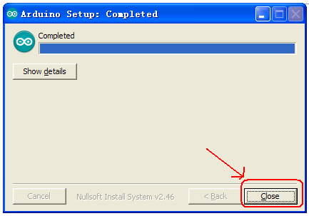
Wait for the installation to be completed, and click close.
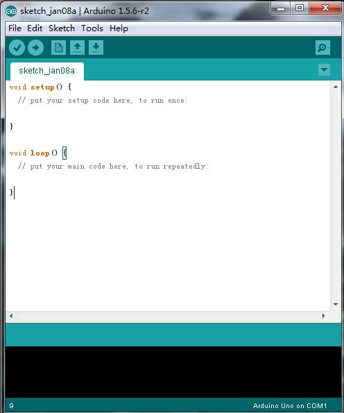
Below is how Arduino 1.5.6 looks like.
Next, let’s install Arduino driver.
For different operating system, there may be slight difference in installation method. Below is an example in WIN 7.
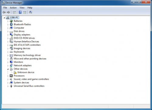
When you connect Arduino Uno to your computer the first time, right click “Computer” —> “Properties”—> “Device manager”, you can see “Unknown devices”.
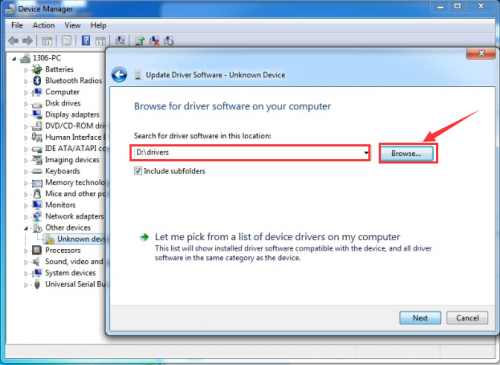
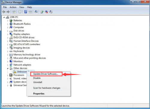
Click “Unknown devices”, select “Update Driver software”.
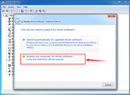
In this page, click “Browse my computer for driver software”.
Click “Next”; select “Install this driver software anyway” to begin the installation.

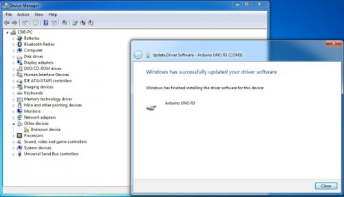
Installation completed; click “Close”.
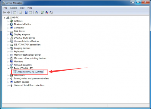
After driver is installed, go to “Device manager” again. Right click “Computer” —> “Properties”—> “Device manager”, you can see UNO device as below figure shows, also the Com port info.
Following is a sketch uploading example called “Hello World!”.
First, open Arduino IDE. In this example sketch, we program Arduino to display “Hello World!” in serial monitor when it receives a specific character string “R”; also the on-board D13 LED will blink once each time it receives “R”.
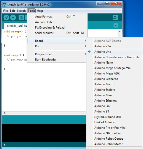
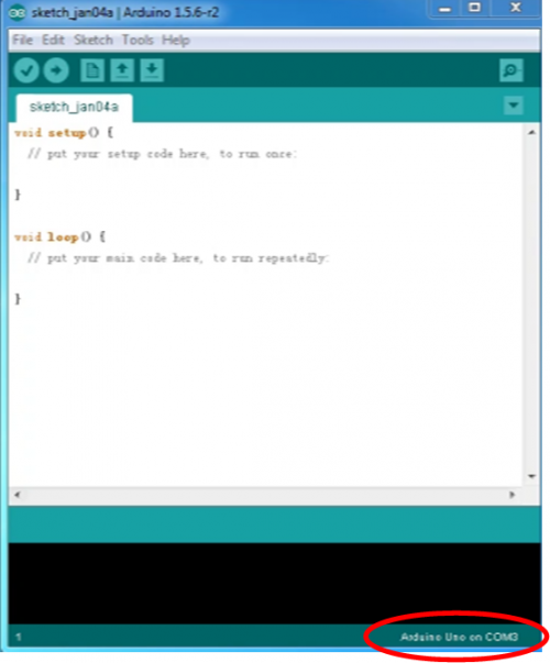
First, set up board; In “Tools”, select “Arduino Uno”.
Next, set up COM port; In “Tools”, select “COM3”.
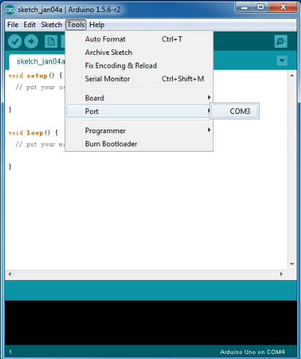
After selection, you can see indicated area is the same with settings in “Device manager”.
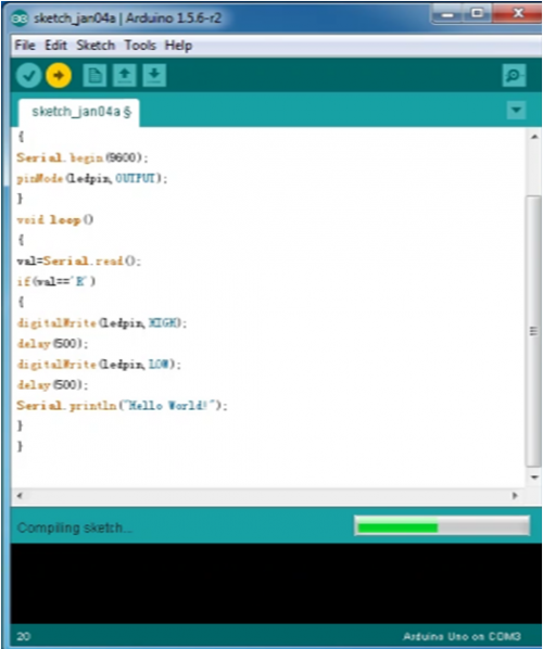
Copy the example sketch and paste it to the IDE; click “Verify ” to check compiling mistakes; click “Upload ” to upload the program to the board.
After uploading is done, open “serial monitor ”; enter “R”; click “Send”, the serial monitor will display “Hello World!” and the D13 LED will blink once.
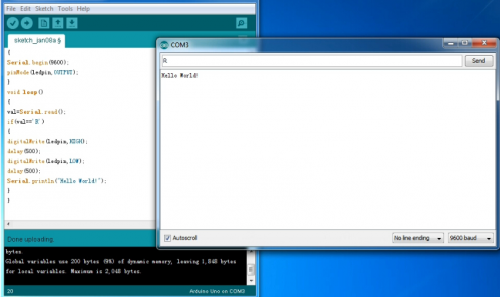
Congratulations! Your first sketch uploading is a success!
Operating video and related material download address: http://7326097.s21d-7.faiusrd.com/0/ABUIABAAGAAggfjavAUopJzsjAI?f=operating+vedio+and+related+material.zip&v=1469496323
5. Introduction of ArduBlock
Ardublock, developed by Shanghai Xinchejian, is a graphical programming environment software. ArduBlock is a third-party software of Arduino’s official programming environment. It can only work with Arduino software. Different from Arduino's text-based programming environment, it's in graphical form. Programming is like building blocks, which makes programming more visualized and interactive. It also greatly lowers the difficulties in programming. People with no programming experience can also compile a program for Arduino controller.
1. Installation Put “ardublock-beta-20140828”this file into the installing catalog of arduino IDE software, if no installing catalog, create one, for example, I put the file in D:\Program Files\Arduino\tools\ArduBlockTool\tool
Download Address of ardublock-beta-20140828: http://7326097.s21d-7.faiusrd.com/0/ABUIABAAGAAg56fbvAUogIzwugc?f=ardublock-beta-20140828.jar&v=1469502439
6. Project Details
After having a basic understanding of Arduino and ArduBlock , we are going to learn graphical programming by actual operation.
Project 1: LED Blinking
Introduction:
This project is one of the basic experiments, which can achieve LED blinking by graphical programming.
Materials Required:
1. KEYESTUDIO UNO Control Board *1
2. V5 Sensor Shield*1
3. Piranha LED*1
4. Female to Female Dupont Line*1
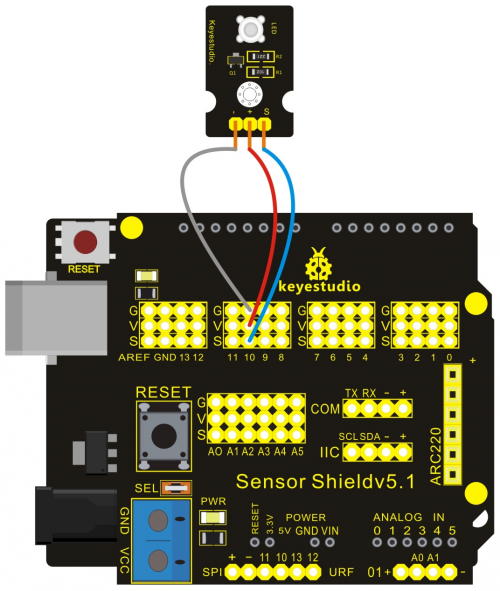
Connection Diagram:
After wiring, we can start programming. We will turn the LED on for one second, and off for one second. This program is simple and similar to one that comes with Arduino except it’s connected to digital pin 10 rather than 13.
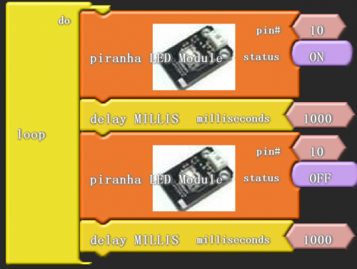
Click “download to Arduino” to see the codes in Arduino interface.
Sample Code:
*****************************************************************************
void setup()
{
  pinMode( 10 , OUTPUT);
}

void loop()
{
  digitalWrite( 10 , HIGH );
  delay( 1000 );
  digitalWrite( 10 , LOW );
  delay( 1000 );
}
*******************************************************************************
Result:
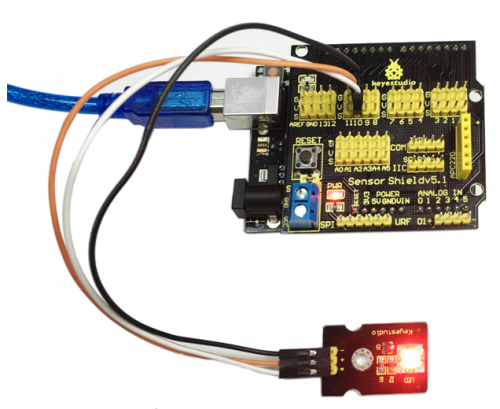
Then, you can see the high brightness LED blinking. We have now finished this project!
Note: Arduino software selection On the TOOLS menu, select UNO. COM port selects the same serial port with the first installation. You cannot download program unless both requirements are met.
Project 2: PWM Regulating Light Brightness
Introduction:
In this project, we should connect signal port of LED module to PWM port, and use graphical programming to control it to produce various PWM signals. So the brightness of LED changes, with effect of breathing LED.
Materials Required:
1. KEYESTUDIO UNO Control Board *1
2. V5 Sensor Shield*1
3. Piranha LED*1
4. Female to Female Dupont Line*3
Connection Diagram:
In this project, we will use PWM to control an LED, slowly lighting it up and then dimming it, and circulate it like this over and over again. Still, connect high bright LED module to pin 10 of digital IO port.
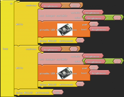
Click “download to Arduino” to see the codes in IDE interface.
Sample Code:
*****************************************************************************
int _ABVAR_1_brightness = 0 ;

void setup()
{
  pinMode( 10 , OUTPUT);
}

void loop()
{
  while ( ( ( _ABVAR_1_brightness ) < ( 255 ) ) )
  {
    _ABVAR_1_brightness = ( _ABVAR_1_brightness + 1 ) ;
    analogWrite(10 , _ABVAR_1_brightness);
    delay( 5 );
  }

  while ( ( ( _ABVAR_1_brightness ) > ( 0 ) ) )
  {
    _ABVAR_1_brightness = ( _ABVAR_1_brightness - 1 ) ;
    analogWrite(10 , _ABVAR_1_brightness);
    delay( 5 );
  }

  delay( 500 );
}
*******************************************************************************
Result:
That’s how we use graphical programming to gradually light the LED up and dim it. Just like the LED is taking a breath. That’s why we vividly call it breathing LED.
Project 3: Flowing Light
Introduction:
In this project, we use graphical programming to control 3 LED module . Light up and dim them according to given sequence and time, gaining a visual effect of flowing light.
Materials Required:
1. KEYESTUDIO UNO Control Board *1
2. V5 Sensor Shield*1
3. Piranha LED*3
4. Female to Female Dupont Line*9
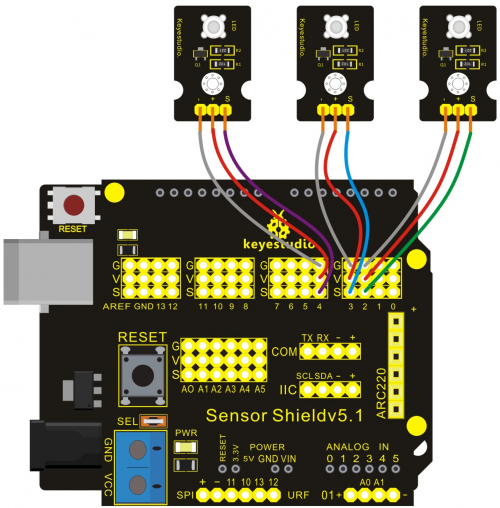
Connection Diagram:
After wiring, we can start programming.
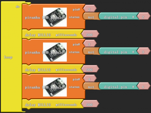
Click “download to Arduino” to see the codes in Aduino interface.
Sample Code:
*****************************************************************************
void setup()
{
  pinMode( 3 , INPUT);
  pinMode( 2 , INPUT);
  pinMode( 4 , INPUT);
  pinMode( 2 , OUTPUT);
  pinMode( 3 , OUTPUT);
  pinMode( 4 , OUTPUT);
}

void loop()
{
  digitalWrite( 2 , !( digitalRead(2) ) );
  delay( 500 );
  digitalWrite( 3 , !( digitalRead(3) ) );
  delay( 500 );
  digitalWrite( 4 , !( digitalRead(4) ) );
  delay( 500 );
}
*******************************************************************************
Result:
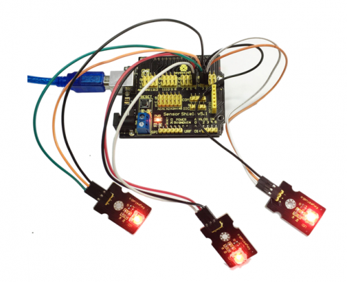
To realize flowing light function, we should connect three high bright LED module of IO port.
Project 4: Button-controlled LED
Introduction:
Button is a common control electrical apparatus element,used to turn-on or turn-off circuit, as a switch of controlling motor or operating other device.
In this project, we use graphical programming to control LED turning on or off.
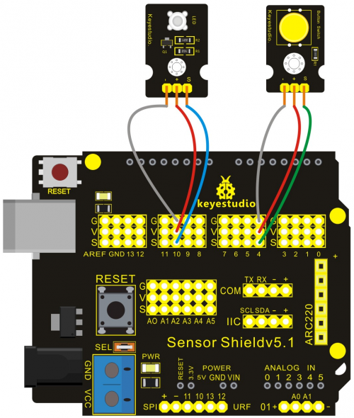
Materials Required:
1. KEYESTUDIO UNO Control Board *1
2. V5 Sensor Shield*1
3. Piranha LED*1
4. Button Module*1
5. Female to Female Dupont Line*6
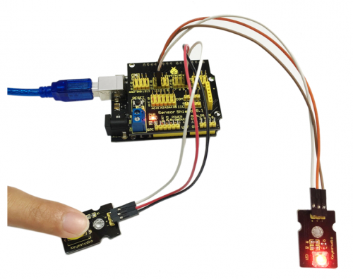
Connection Diagram:
After wiring, we can start programming.
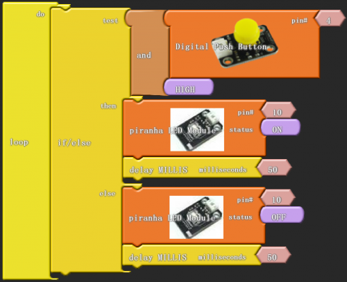
Click “download to Arduino” to see the following codes in IDE interface:
Sample Code:
*****************************************************************************
void setup()
{
  pinMode( 4 , INPUT);
  pinMode( 10 , OUTPUT);
}

void loop()
{
  if (( digitalRead(4) && HIGH ))
  {
    digitalWrite( 10 , HIGH );
    delay( 50 );
  }
  else
  {
    digitalWrite( 10 , LOW );
    delay( 50 );
  }
}
*******************************************************************************
Result:
After finishing downloading, we can control LED by button module.
Project 5: Passive Buzzer Sound Production
Introduction:
Buzzers are divided into active and passive buzzers. Passive buzzers don’t carry with vibrator inside, so it need external sine or square wave to drive. It can produces slight sound when connecting directly to power supply. It features controlling sound frequency and producing the sound of “do re mi fa so la si”.
In this project, with passive buzzer, we use graphical programming to make this buzzer produce sound at 10~5000 frequency.
Materials Required:
1. KEYESTUDIO UNO Control Board *1
2. V5 Sensor Shield*1
3. Passive buzzer*1
4. Female to Female Dupont Line*3
Connection Diagram:
After wiring, we can start programming.
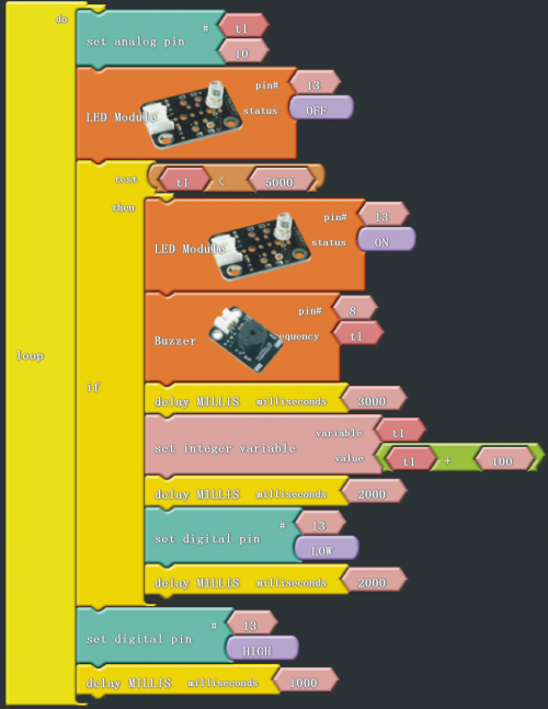
Click “download to Arduino” to see the following codes in IDE interface:
Sample Code:
*****************************************************************************
int _ABVAR_1_t1;

void setup()
{
pinMode( 13 , OUTPUT);
_ABVAR_1_t1 = 0;
}

void loop()
{
analogWrite(_ABVAR_1_t1, 10);
digitalWrite( 13 , !(LOW ));
if (( ( _ABVAR_1_t1 ) < ( 5000 ) ))
{
digitalWrite( 13 , !(HIGH ));
tone(8, _ABVAR_1_t1, 3000);
_ABVAR_1_t1 = ( _ABVAR_1_t1 + 100 ) ;
delay( 2000 );
digitalWrite( 13 , LOW );
delay( 2000 );
}
digitalWrite( 13 , HIGH );
delay( 1000 );
}

*******************************************************************************
Result:
Ardublock graphical programming environment offers a buzzer module. There are several parameters, including one buzzer connecting port, and the other one sound frequency.In this project, t1 is a variable to change the frequency of sound producing, which begins from 10, and increases 100 each time, up to 5000. Figure pin 13 is used as prompt, so when making a sound , LED blinks. “Dang”module is a cycle structure on condition that the value of t1 is less than 5000. When more than 5000, the cycle structure ends. Please have a try, to find in which frequency the sound is sweeter from 10 to 5000 in this mystical sound program.
After downloading the program, this passive buzzer project is finished.
Project 6: Active Buzzer Sound Production
Introduction:
Buzzers are divided into active and passive buzzers. Active buzzer can produce sound normally when connecting directly to power supply, usually with stable frequency.
In this project, with active buzzer, we use graphical programming to make buzzer ring for 1s and stop for 1s, circulating like this.
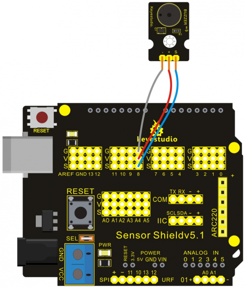
Materials Required:
1. KEYESTUDIO UNO Control Board *1
2. V5 Sensor Shield*1
3. Active Buzzer*1
4. Female to Female Dupont Line*3
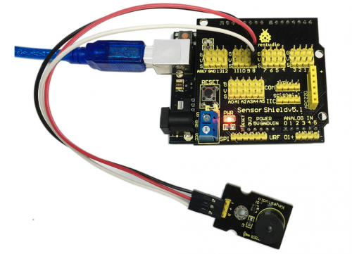
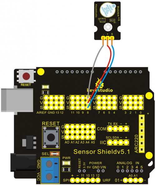
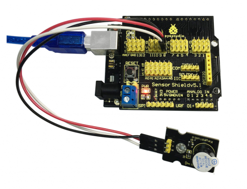
Connection Diagram:
After wiring, we can start programming.
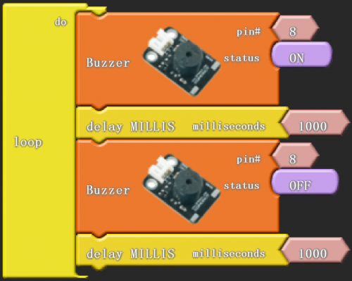
Click “download to Arduino” to see the following codes in IDE interface:
Sample Code:
*****************************************************************************
void setup()
{
  pinMode( 8 , OUTPUT);
}

void loop()
{
  digitalWrite( 8 , HIGH );
  delay( 1000 );
  digitalWrite( 8 , LOW );
  delay( 1000 );
}
*******************************************************************************
Result:
Then buzzer rings for 1 second and stop for 1 second, circulating like this.
Project 7: Reading-out Analog Value
Introduction:
On a KEYESTUDIO UNO control board , there are 6 analog interfaces numbered from 0 to 5.
Potentiometer is a typical output component of analog value. We will use it in this project.
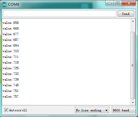
We simply use graphical programming read out analog value of analog 0 on serial monitor.
Materials Required:
1. KEYESTUDIO UNO Control Board *1
2. V5 Sensor Shield*1
3. Adjustable Potentiometer*1
4. Female to Female Dupont Line*3
Connection Diagram:
After wiring, we can start programming.

Click “download to Arduino” to see the following codes in IDE interface:
Sample Code:
*****************************************************************************
void setup()
{
  Serial.begin(9600);
}

void loop()
{
  Serial.print("value:");
  Serial.print(analogRead(0));
  Serial.println();
  delay( 1000 );
}

*******************************************************************************
Result:
There are reading-out analog values as follow.
Project 8: Light-controlled Sound
Introduction:
Photovaristor is a resistor using the photoelectric effect of a semiconductor. Its resistance changes along with the intensity of the incident light, the greater the intensity, the lower the resistance, the less the intensity, the higher the resistance. It has wide application in various light-controlled circuits, such as lighting control, regulation, light-controlled switch etc.
In this project, we use graphical programming to display analog value of illumination intensity measured by photovaristor. And set this value as frequency of sound production.
Materials Required:
1. KEYESTUDIO UNO Control Board *1
2. V5 Sensor Shield*1
3. Photovaristor Module*1
4. Photovaristor Module
5. Female to Female Dupont Line*6
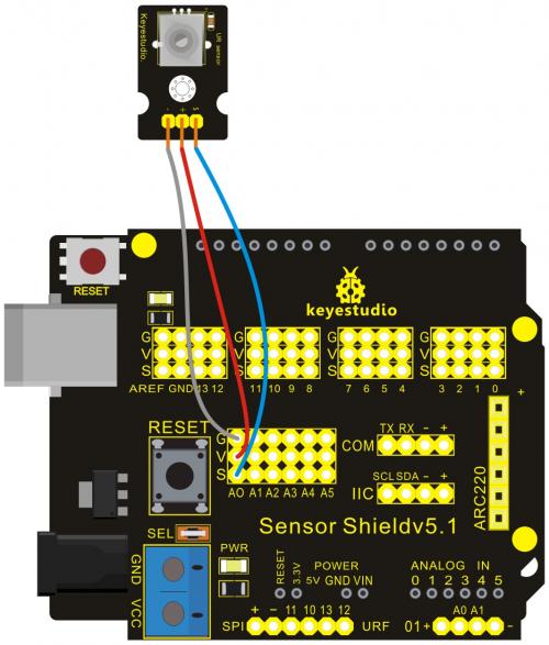
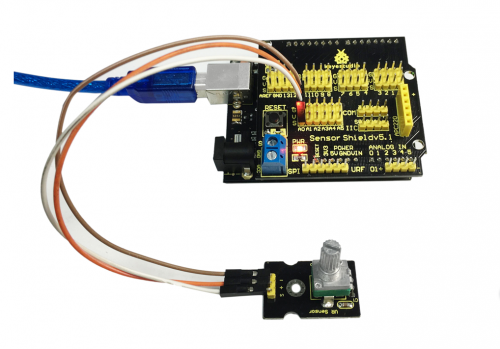
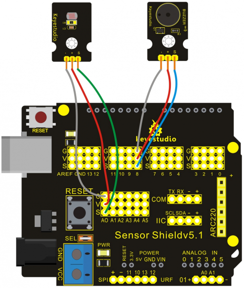
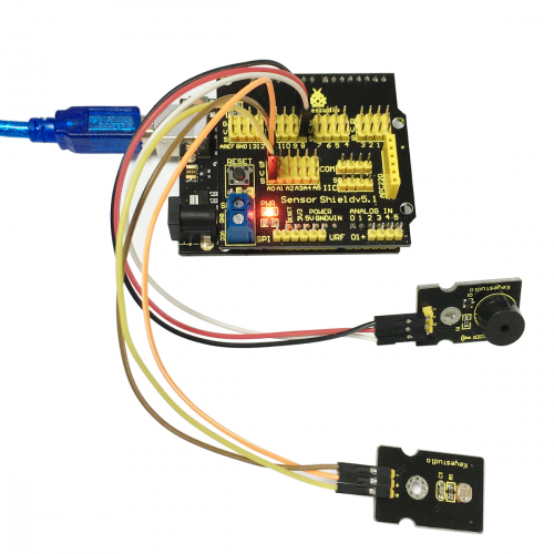
Connection Diagram:
After wiring, we can start programming.
In this project, we apply similar method in "reading analog value". Directly connect the photovaristor to analog port. The analog value varies with the intensity of light and controls the sound frequency produced by passive buzzer.
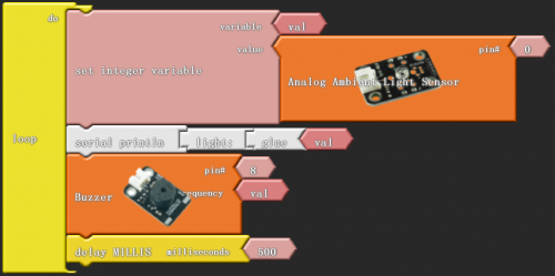
Click “download to Arduino” to see the following codes in IDE interface:
Sample Code:
*****************************************************************************
int _ABVAR_1_val = 0 ;

void setup()
{
  Serial.begin(9600);
}

void loop()
{
  _ABVAR_1_val = analogRead(0) ;
  Serial.print("light:");
  Serial.print(_ABVAR_1_val);
  Serial.println();
  tone(8, _ABVAR_1_val);
  delay( 500 );
}
*******************************************************************************
Result:
After downloading the program, have a kook at the value of serial monitor.
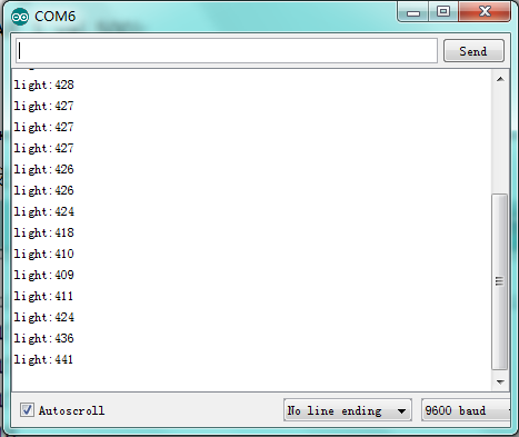
The value indicates the light intensity, and the larger the value,the stronger the light intensity. Meanwhile, the value belongs to the sound frequency produced by passive buzzer.
Project 9: Sound-controlled Light
Introduction:
Sound sensor is used to detect the intensity of ambient sound; the intensity is proportional to output voltage.
In this project, we use graphical programming to read out analog value of sound intensity measuring by sound module, ranging from 0 to 1023. And then map the value to 0-255, displaying on serial monitor. Finally set the mapped value as PwM value to control brightness of LED.
Materials Required:
1. KEYESTUDIO UNO Control Board *1
2. V5 Sensor Shield*1
3. Piranha LED*1
4. Sound Module*1
5. Female to Female Dupont Line*6
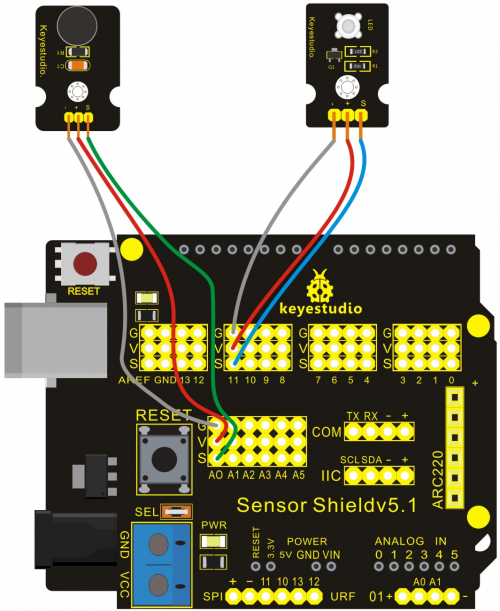
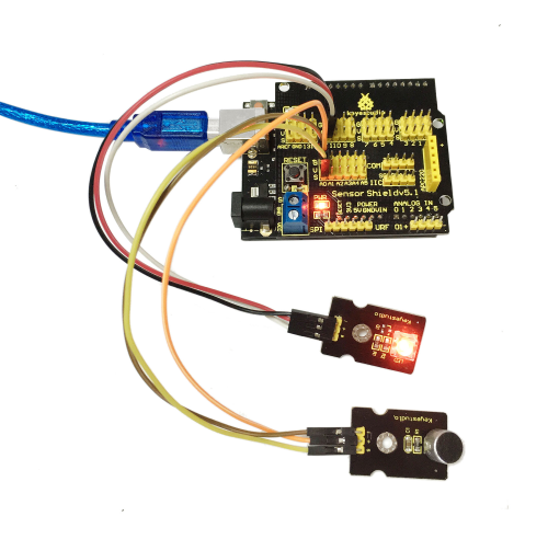
Connection Diagram:
After wiring, we can start programming.
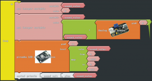
Click “download to Arduino” to see the codes in IDE interface:
Sample Code:
*****************************************************************************
int _ABVAR_1_sound_value = 0 ;

void setup()
{
  pinMode( 11 , OUTPUT);
  Serial.begin(9600);
}

void loop()
{
  _ABVAR_1_sound_value = 0 ;
  _ABVAR_1_sound_value = ( _ABVAR_1_sound_value + analogRead(0) ) ;
  analogWrite(11 , map ( _ABVAR_1_sound_value , 0 , 1023 , 0 , 255 ) );
  Serial.print("sound val:");
  Serial.print(_ABVAR_1_sound_value);
  Serial.println();
}
*******************************************************************************
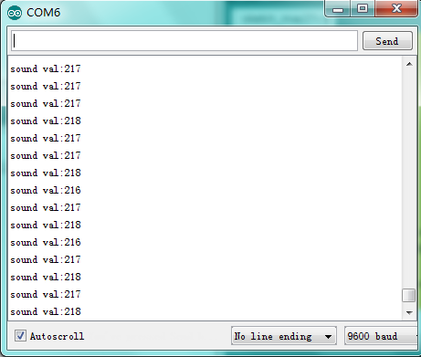
Result:
After downloading program, have a look at values on serial monitor.
Project 10: Servo Motor Control
Introduction:
Servomotor is a commonly used positional-servo actuator.
In this project, we use graphical programming . First , read out analog value controlled by adjustable potentiometer module, ranging from 0 to 1023. Then, map the value to 0-180. Finally, set the mapped value as angle of motor rotation.
Materials Required:
1. KEYESTUDIO UNO Control Board *1
2. V5 Sensor Shield*1
3. Adjustable Potentiometer*1
4. Micro Servo*1
5. Female to Female Dupont Line*3
Connection Diagram:
Note: do not use the USB port for power supply because the current it needs is more than 500ma,it may lead to USB port burnt out. We recommend external power supply.
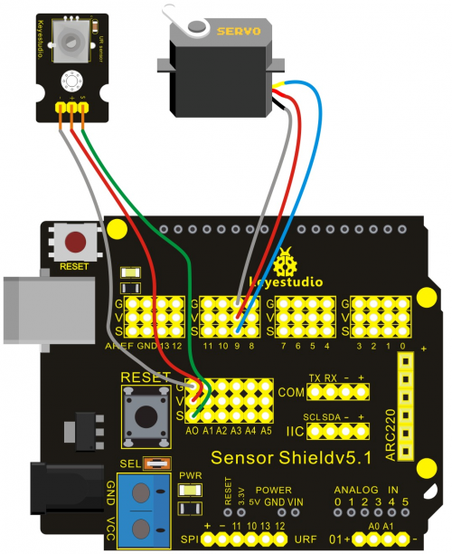
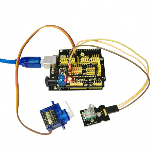
After wiring, we can start programming.
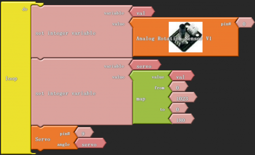
Click “download to Arduino” to see the codes in Arduino interface.
Sample Code:
*****************************************************************************
#include <Servo.h>
int _ABVAR_1_val = 0 ;
int _ABVAR_2_servo = 0 ;
Servo servo_pin_9;

void setup()
{
  servo_pin_9.attach(9);
}

void loop()
{
  _ABVAR_1_val = analogRead(0) ;
  _ABVAR_2_servo = map ( _ABVAR_1_val , 0 , 1023 , 0 , 180 )  ;
  servo_pin_9.write( _ABVAR_2_servo );
}
*******************************************************************************
Result:
Put the program into the development, and we can use potentiometer to control servomotor.
Note:place Servo folder into the compiler of \Arduino\libraries. Otherwise, you can’t compile. Just like this D:\Program Files\Arduino\libraries
Servo folder downloading address:
http://7326097.s21d-7.faiusrd.com/0/ABUIABAAGAAggrHXvAUopNrTggY?f=Servo.zip&v=1469438082
Project 11:Ultrasonic Distance Measurement
Introduction:
In this project, we use graphical programming to measure the distance between ultrasonic module and front obstacle and display it on serial monitor.
Materials Required:
1. KEYESTUDIO UNO Control Board *1
2. V5 Sensor Shield*1
3. Ultrasonic Module*1
4. Female to Female Dupont Line*4
Connection Diagram:
Let’s start experiment, and connect ultrasonic waves to ARDUINO referring to the following figure.

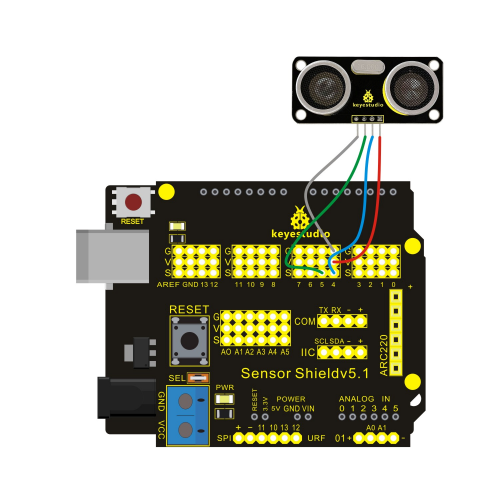
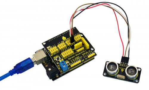
After wiring, we can start programming.

Click “download to Arduino” to see the following codes in ARDUINO programming interface:
Sample Code:
*****************************************************************************
int _ABVAR_1_t1 = 0 ;
int ardublockUltrasonicSensorCodeAutoGeneratedReturnCM(int trigPin, int echoPin)
{
  long duration;
  pinMode(trigPin, OUTPUT);
  pinMode(echoPin, INPUT);
  digitalWrite(trigPin, LOW);
  delayMicroseconds(2);
  digitalWrite(trigPin, HIGH);
  delayMicroseconds(20);
  digitalWrite(trigPin, LOW);
  duration = pulseIn(echoPin, HIGH);
  duration = duration / 59;
  if ((duration < 2) || (duration > 300)) return false;
  return duration;
}

void setup()
{
  digitalWrite( 4 , LOW );

  Serial.begin(9600);
}

void loop()
{
  _ABVAR_1_t1 = 	ardublockUltrasonicSensorCodeAutoGeneratedReturnCM( 4 , 5 ) ;
  Serial.print("diatance:");
  Serial.print(_ABVAR_1_t1);
  Serial.println();
  delay( 200 );
}
*******************************************************************************
Result:
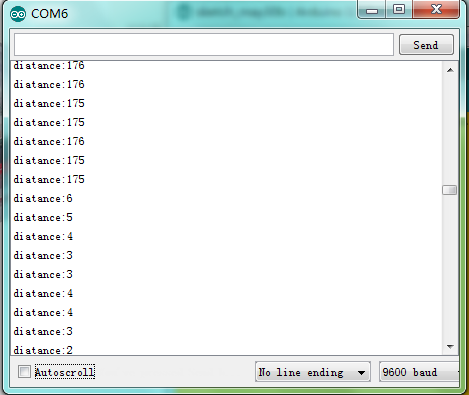
We can see the distance value measured by ultrasonic in the serial monitor of ARDUINO after downloading the program.
Project 12:PS2 Joystick Module
Introduction:
The joystick sensor module uses original high-quality metal PS2 joystick potentiometer, with (X, Y) 2-axis analog output and (Z) 1-channel button digital output. Together with Arduino sensor shield, you can make a remote control or other interactive projects.
In this project , we use graphical programming to read out analog output of X, Y axis, and digital output of Z axis, displaying them on serial monitor.
Materials Required:
1. KEYESTUDIO UNO Control Board *1
2. V5 Sensor Shield*1
3. Joystick Module*1
4. Female to Female Dupont Line*5
Connection Diagram:
Let’s start experiment, and connect ultrasonic waves to ARDUINO referring to the following figure.
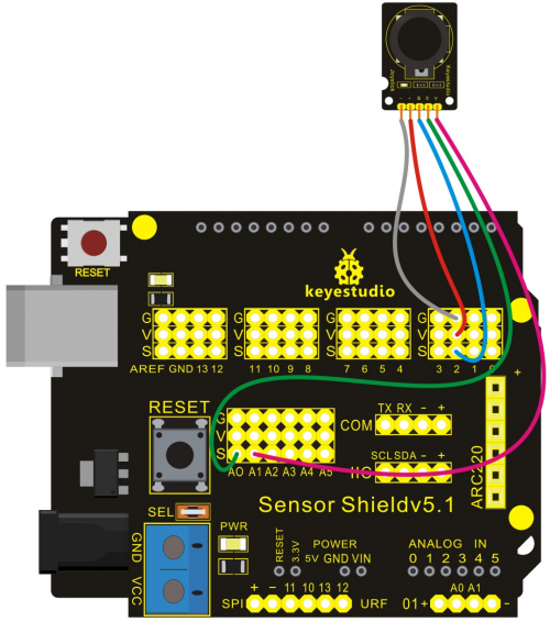
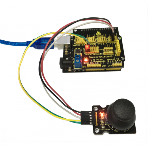
After wiring, we can start programming.
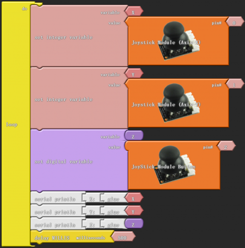
Click “download to Arduino” to see the following codes in ARDUINO programming interface:
Sample Code:
*****************************************************************************
int _ABVAR_1_X = 0 ;
int _ABVAR_2_Y = 0 ;
bool _ABVAR_3_Z= false ;

void setup()
{
  pinMode( 2 , INPUT);
  Serial.begin(9600);
}

void loop()
{
  _ABVAR_1_X = analogRead(0) ;
  _ABVAR_2_Y = analogRead(1) ;
  _ABVAR_3_Z = digitalRead(2) ;
  Serial.print("X:");
  Serial.print(_ABVAR_1_X);
  Serial.println();
  Serial.print("Y:");
  Serial.print(_ABVAR_2_Y);
  Serial.println();
  Serial.print("Z:");
  Serial.print(_ABVAR_3_Z);
  Serial.println();
  delay( 500 );
}
*******************************************************************************
Result:
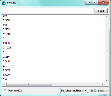
After downloading the program, we can see X and Y axis value and Z axis high and low level of joystick module in ARDUINO serial monitor.
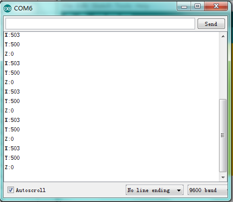
Apply X and Y axis of joystick module, press Z axis and you can see obviously the change of numbers.
Project 13: LM35 Temperature Sensor
Introduction:
LM35 is a common and easy-to-use temperature sensor.
In this project, we use graphical programming to read out analog value of temperature measured by LM35 temperature sensor module. Then after a serials of calculation we get specific temperature value. Finally display the value on serial monitor.
Materials Required:
1. KEYESTUDIO UNO Control Board *1
2. V5 Sensor Shield*1
3. LM35 Temperature Module*1
4. Female to Female Dupont Line*3
Connection Diagram:
Let’s start experiment, and connect ultrasonic waves to ARDUINO referring to the following figure.
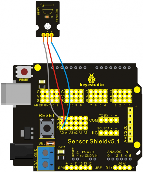
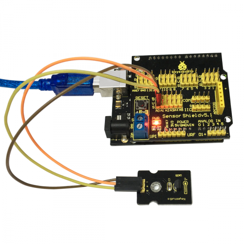
After wiring, we can start programming.
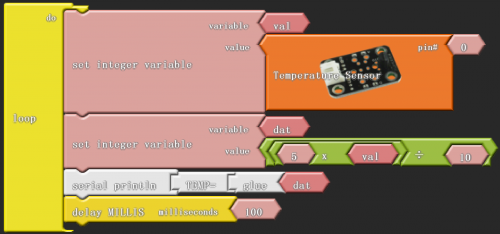
Click “download to Arduino” to see the following codes in ARDUINO programming interface:
Sample Code:
*****************************************************************************
int _ABVAR_1_val = 0 ;
int _ABVAR_2_dat = 0 ;

void setup()
{
  Serial.begin(9600);
}

void loop()
{
  _ABVAR_1_val = analogRead(0) ;
  _ABVAR_2_dat = ( ( 5 * _ABVAR_1_val ) / 10 ) ;
  Serial.print("TEMP=");
  Serial.print(_ABVAR_2_dat);
  Serial.println();
  delay( 100 );
}
*******************************************************************************
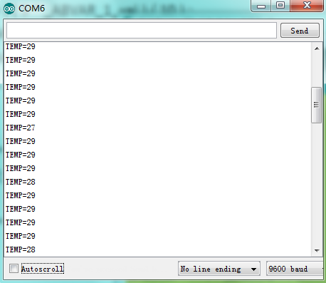
Result:
After the program is downloaded, you can open the serial monitor to see current temperature.
Project 14: 5V Relay Module
Introduction:
Relay is a automatic control device, the output of which can produce saltatory changes when the input(electricity, magnetism, sound, light and heat) arrives at a certain value. We usually need to use weak current to control strong current in life, namely, the low current controls large current. It looks like when Arduino controller control high power electric appliances like fan, we have to use relay.
In this project, we use graphical programming to control the on and off of 1-channel relay easily. The relay is on for 0.5S and off for 0.5S with an interval of 0.5S, circulating like this.
Materials Required:
1. KEYESTUDIO UNO Control Board *1
2. V5 Sensor Shield*1
3. 5V 1-channel Relay Module*1
4. Female to Female Dupont Line*3
Connection Diagram:
Let’s start experiment, and connect ultrasonic waves to ARDUINO referring to the following figure.


After wiring, we can start programming.
The relay works in high level, and we use digital port 3 in the Arduino controller. Output high level for 0.5 seconds, and then output low level for 0.5 seconds. That is to say, turn on switch for 0.5 seconds and turn off for 0.5 seconds.
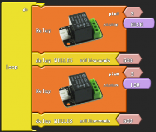
Click “download to Arduino” to see the following codes in ARDUINO programming interface:
Sample Code:
*****************************************************************************
void setup()
{
  pinMode( 3 , OUTPUT);
}

void loop()
{
  digitalWrite( 3 , HIGH );
  delay( 500 );
  digitalWrite( 3 , LOW );
  delay( 500 );
}
*******************************************************************************
Result:
Next, we can see the indicator light of the relay blinking when switch-on and off. Turn on switch for 0.5 seconds,and the led is on; turn off for 0.5 seconds and the led is off ; meanwhile, the relay is ticking.
Project 15: Tilting Switch Module
Introduction:
When one side of the switch tilts below horizontal position, the switch is on; When the other side of the switch tilts below horizontal position, the switch is off.
In the project, we use graphical programming to control the on and off of LED, tilting module used as a button.
Materials Required:
1. KEYESTUDIO UNO Control Board *1
2. V5 Sensor Shield*1
3. Piranha LED*1
4. Tilting Switch Module*1
5. Female to Female Dupont Line*6
After wiring, we can start programming.
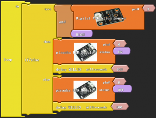
Click “download to Arduino” to see the following codes in IDE interface:
Sample Code:
*****************************************************************************
void setup()
{
  pinMode( 3 , INPUT);
  pinMode( 6 , OUTPUT);
}

void loop()
{
  if (( digitalRead(3) && HIGH ))
  {
    digitalWrite( 6 , HIGH );
    delay( 100 );
  }
  else
  {
    digitalWrite( 6 , LOW );
    delay( 100 );
  }
}
*******************************************************************************
Result:
After the program is downloaded, we can use tilting switch module to control LED.
Project 16: Capacitive Touch Module Control LED
Introduction:
Capacitance touch module supplies one touch key to detect IC. In order to replace traditional key with changeable area key, touch detecting IC is designed.
In this project, we use graphical programming and control the on and off of LED by capacitive touch module.
Materials Required:
1. KEYESTUDIO UNO Control Board *1
2. V5 Sensor Shield*1
3. Piranha LED*1
4. Copacitive Touch Module*1
5. Female to Female Dupont Line*6
After wiring, we can start programming.
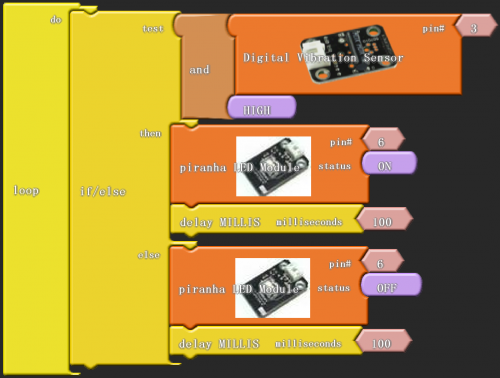
Click “download to Arduino” to see the following codes in IDE interface:
Sample Code:
*****************************************************************************
void setup()
{
  pinMode( 4 , INPUT);
  pinMode( 10 , OUTPUT);
}

void loop()
{
  if (( digitalRead(4) && HIGH ))
  {
    digitalWrite( 10 , LOW );
  }
  else
  {
    digitalWrite( 10 , HIGH );
  }
}
*******************************************************************************
Result:
After the program is downloaded, we can use capacitive touching module to control LED.
Project 17: Flame Alarm Module
Introduction:
Infrared ray is very sensitive to flame, which is the feature of flame sensor. It utilizes specific infrared receive tube to detect flame, and then converts the brightness into changed level signal.
In this project, we use graphical programming and flame sensor to control the ringing and stop of a buzzer.
Materials Required:
1. KEYESTUDIO UNO Control Board *1
2. V5 Sensor Shield*1
3. Flame Sensor*1
4. Active Buzzer*1
5. Female to Female Dupont Line*3
After wiring, we can start programming.
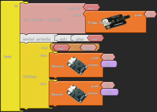
Click “download to Arduino” to see the following codes in IDE interface:
Sample Code:
*****************************************************************************
int _ABVAR_1_val = 0 ;

void setup()
{
  Serial.begin(9600);
  pinMode( 10 , OUTPUT);
}

void loop()
{
  _ABVAR_1_val = analogRead(0) ;
  Serial.print("val:");
  Serial.print(_ABVAR_1_val);
  Serial.println();
  if (( ( _ABVAR_1_val ) < ( 600 ) ))
  {
    digitalWrite( 10 , HIGH );
  }
  else
  {
    digitalWrite( 10 , LOW );
  }
}
*******************************************************************************
Result:
After the program is downloaded, we can use flame sensor to check whether there is flame around.
Project 18: Reed Switch Module
Introduction:
The reed switch grass tube is full of highly purified inactive gas. Before operating, the two reeds are separated. Extra magnetic field produces different polarity around the endpoint of the two reeds, so that two different polar reeds attract each other and close.
In this project, we use graphical programming and regard reed switch module and magnet as a switch to control the on and off of LED.
Materials Required:
1. KEYESTUDIO UNO Control Board *1
2. V5 Sensor Shield*1
3. Piranha LED*1
4. Reed Switch Module*1
5. Female to Female Dupont Line*6
After wiring, we can start programming.
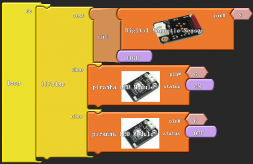
Click “download to Arduino” to see the following codes in IDE interface:
Sample Code:
*****************************************************************************
void setup()
{
  pinMode( 3 , INPUT);
  pinMode( 6 , OUTPUT);
}

void loop()
{
  if (( digitalRead(3) && HIGH ))
  {
    digitalWrite( 6 , HIGH );
  }
  else
  {
    digitalWrite( 6 , LOW );
  }
}
*******************************************************************************
Result:
After downloading is done, you can check whether there is magnetic field using reed switch module.
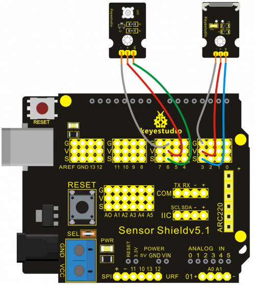
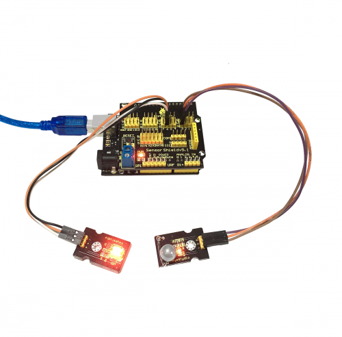
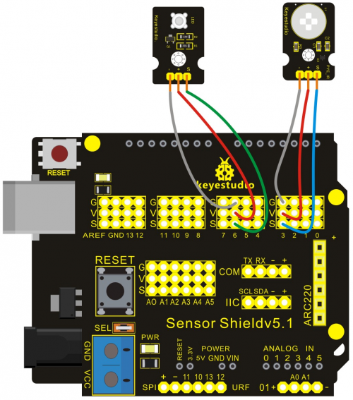
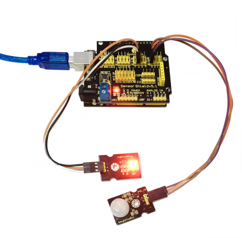
Project 19: Human Body IR Pyroelectricity
Introduction:
It is a human body detecting sensor based on infrared pyroelectricity, which can only detect moving body. That is to say, when you don’t move, it can do nothing. Still ,it is a digital sensor.
In this project, we use graphical programming and regard human body IR pyroelectricity and human body as a button to control the on and off of LED.
Materials Required:
1. KEYESTUDIO UNO Control Board *1
2. V5 Sensor Shield*1
3. Piranha LED*1
4. Human Body IR Pyroelectricity*1
5. Female to Female Dupont Line*6
After wiring, we can start programming.
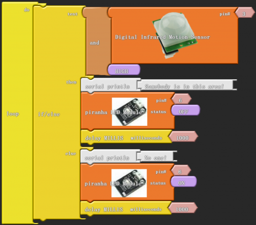
Click “download to Arduino” to see the following codes in IDE interface:
Sample Code:
*****************************************************************************
void setup()
{
  pinMode( 3 , INPUT);
  Serial.begin(9600);
  pinMode( 6 , OUTPUT);
}

void loop()
{
  if (( digitalRead(3) && HIGH ))
  {
    Serial.print("Somebody is in this area!");
    Serial.println();
    digitalWrite( 6 , LOW );
    delay( 1000 );
  }
  else
  {
    Serial.print("No one!");
    Serial.println();
    digitalWrite( 6 , HIGH );
    delay( 1000 );
  }
}
*******************************************************************************
Result:
After the downloading is done, use reed switch module to check whether there is someone moving. If someone moving, piranha LED on and the serial monitor indicates “Somebody is in this area!”; if nobody moving, the LED off and the serial monitor indicates "No one!".
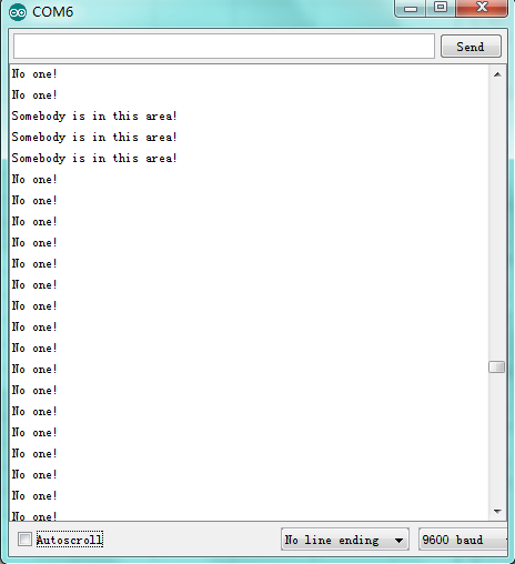
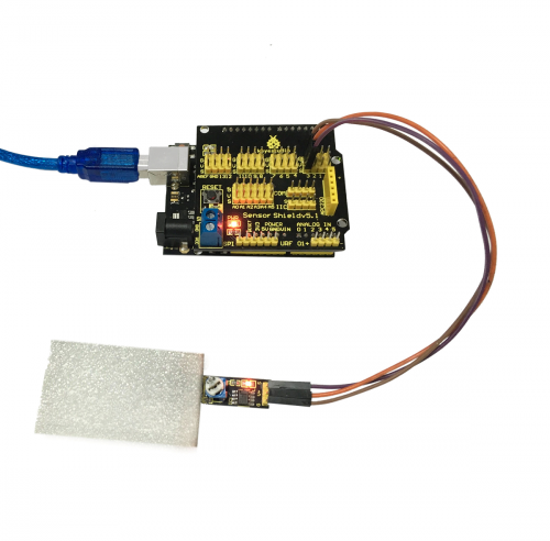
Project 20: Line Tracking Sensor
Introduction:
Line tracking sensor has a TCRT5000 photoelectric sensor. Infrared reflectivity of color is different ,which is applied to convert strong and weak echoed signal into current signal by photoelectric sensor. The potentiometer is used to adjust sensitivity of this sensor.
In this project, we use graphical programming to detect high and low level of line tracking sensor signal port and the color of objects, displaying it on serial monitor.
Materials Required:
1. KEYESTUDIO UNO Control Board *1
2. V5 Sensor Shield*1
3. Line Tracking Sensor*1
4. Female to Female Dupont Line*3
After wiring, we can start programming.

Click “download to Arduino” to see the following codes in IDE interface:
Sample Code:
*****************************************************************************
void setup()
{
  pinMode( 3 , INPUT);
  Serial.begin(9600);
}

void loop()
{
  Serial.print("Line Tracking");
  Serial.print(digitalRead(3));
  Serial.println();
  delay( 1000 );
}
*******************************************************************************
Result:
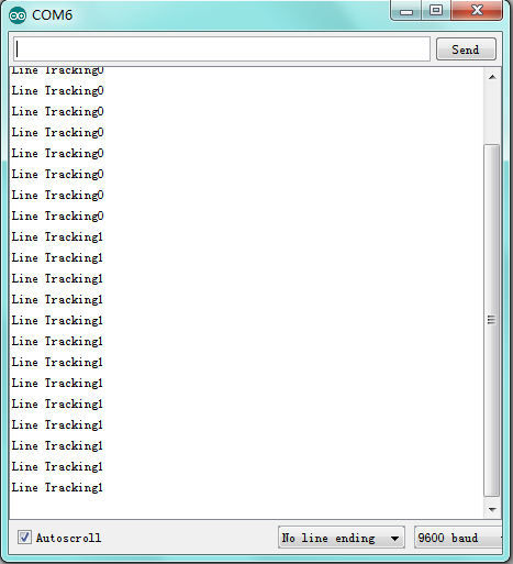
After downloading program, we can use line tracking sensor to detect the color of line tracking object. If it is white, the light on the sensor turns on, and display “Line Tracking0” on serial monitor;if black, the light off, and display “Line Tracking1”
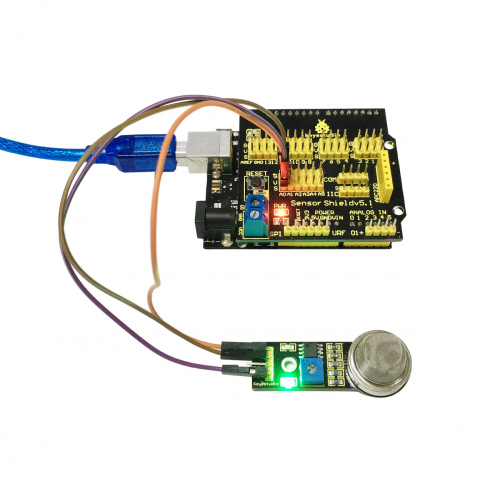
Project 21: MQ-2 Combustible Gas and Smoke Sensor
Introduction:
Arduino MQ-2 combustible gas sensor is mainly used to detect whether the gas leaks in industry and family. It can detect liquefied petroleum gas, methane, ethane, iso-butane, ethyl alcohol, hydrogen, smoke and ect. Potentiometer can be used to adjust the sensitivity of the sensor.
In this project, we use graphical programming to detect analog value of signal port of this sensor. When gases leak, the value increases and the LED is on .
Materials Required:
1. KEYESTUDIO UNO Control Board *1
2. V5 Sensor Shield*1
3. MQ-2 Combustible Gas and Smoke Sensor*1
4. Female to Female Dupont Line*3
After wiring, we can start programming.

Click “download to Arduino” to see the following codes in IDE interface:
Sample Code:
*****************************************************************************
void setup()
{
  Serial.begin(9600);
}

void loop()
{
  Serial.print("sensorValue;");
  Serial.print(analogRead(0));
  Serial.println();
  delay( 1000 );
}
*******************************************************************************
Result:
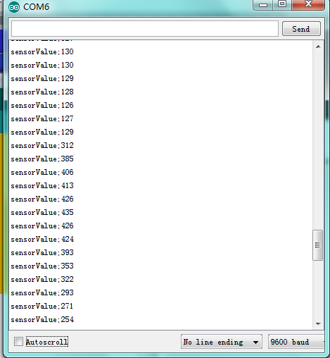
After downloading program, you can use this sensor to detect whether the gas leaks. Open serial monitor, you can see the analog value of ambient gas. In this experiment, we detect the gas of a lighter. Open a lighter and close to the sensor after closing it, the analog increasing, and the red light on the sensor is on; the lighter away from this sensor, the analog value decreasing, the red light off.
Project 22: Soil Module
Introduction:
This is an easy moisture sensor detecting the moisture of soil. If soil is lack of water, the output analog value decreases; if not, the value increases.
In this project, we use graphical programming to detect analog value of signal port of this sensor, displaying it on serial monitor.
Materials Required:
1. KEYESTUDIO UNO Control Board *1
2. V5 Sensor Shield*1
3. Soil Module*1
4. Female to Female Dupont Line*3
After wiring, we can start programming.

Click “download to Arduino” to see the following codes in IDE interface:
Sample Code:
*****************************************************************************
void setup()
{
  Serial.begin(9600);
}

void loop()
{
  Serial.print("sensorValue:");
  Serial.print(analogRead(0));
  Serial.println();
  delay( 1000 );
}
*******************************************************************************
Result:
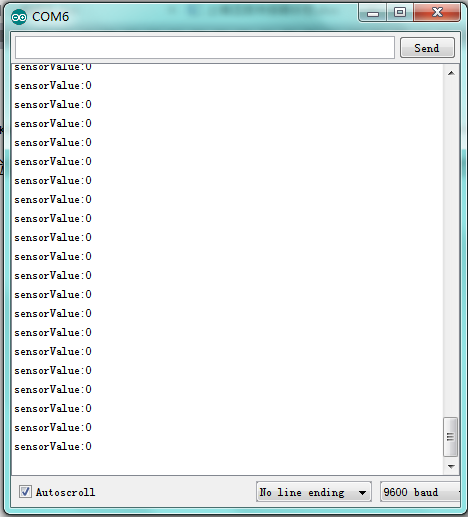
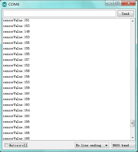
After downloading program, we can use soil module to detect moisture in the soil. Open serial monitor , we can see corresponding value.
This is a printscreen under normal situation.
This is a printscreen when putting soil module into water.
Download address of all courses:
http://7326097.s21d-7.faiusrd.com/0/ABUIABAAGAAg27TXvAUogIqf-wE?f=program+download+address+of+all+courses.zip&v=1469438555
Referred Website:
http://blog.ardublock.com/
Resources
Video
http://www.keyestudio.com/wp/2016/11/ks0086/
https://drive.google.com/open?id=115xKZQdaq4m-M7egOj_d0cWNGqvg4gYv
