Ks0364 keyestudio Smart Little Turtle Robot V2.0
Intorduction
When you tell your child how beautiful the world is, it is better to take him directly to feel it; when the child asks you why the small alarm clock always sings, it is better to open the alarm clock and explore the secret of the sound with your child. When your child has a desire for a robot gift, you might do it with him as well! Now with ARDUINO, everything is impossible.
Arduino is a convenient, flexible and easy-to-use open source electronic prototyping platform, which is suitable for entry-level developers who are new to hardware.
Now our keyestudio team has upgraded the turtle robot based on the turtle generation1, adding some more interesting features. Let you enjoy the DIY fun and programming while learning with your child.
keyestudio Smart Little Turtle V2.0 is an enhanced kit based on easy-to-use and flexible Arduino platform.
You are able to learn how to get started with both Arduino platform and Mixly block coding.
We provide you with complete tutorials of Arduino programming language and Mixly Graphical program to control the smart turtle robot, achieving the functions of line tracking, automatic obstacle avoidance, Bluetooth control and infrared remote control.
Furthermore, it adds a 8*8 matrix that can show you the running states of robot. The wiring for the turtle robot is more simple.You can easily build the robot with a little or even no programming experience.
Parameters
- Motor’svoltage range: 1-6V; motor shaft length: 10mm; speed: 6.0V 100rpm/min.
- Motor control is driven by L298P.
- Three groups of line tracking modules, to detect black-white line with higher accuracy and can also be used for anti-fall control.
- Ultrasonic module is used to detect whether there is obstacles or not.
- Bluetooth wireless modulecan be paired with Bluetooth device on phone to remotely control the turtle robot.
- Infrared receiver modulematches with an infrared remote control to control the turtle robot.
- Add a 8*8 dot matrix module, showing the robot states.
- Can access to the external voltage 6~ 12V
Component List
When get this turtle robot kit, at first glance, you will see the beautiful big packaging box. And each component is tidily packed inside the small box. What components you should get to build the robot? We have listed all the components as follows:
Assembly Guide
When all the components have been counted well, cannot wait to assemble it? Follow the assembly steps here to build your own robot.
(1) How to get started with? Begin with the bottom parts.
Firstly, you should prepare the components as follows:
- M3*6MM round-head screw *2
- Nut M3 nickle plating *2
- Bottom PCB*1
- Tracking sensor *1
- Universal caster *2
Project Details for Turtle Robot
Project 1: Getting Started with ARDUINO
1)Core Part of Robot
When it comes to the core part, you may think of the sparkling energy block on the front of Iron Man's chest, or something in R2D2 Robot's head that can make him talk nonsense. The core is the part that really matters today. In fact, it is very easy to understand the core. In other word, the core is just like the human brain. It can receive various kinds of information every day and will send out various instructions every day. So actually the core of our robot is a development board compatible with ARDUINO.
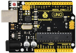
Well, let's first look at this development board as the figure shown below:
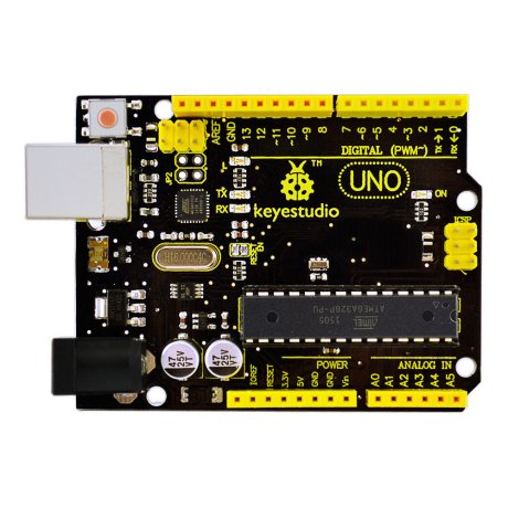
So why choose to use the UNO R3 development board as the core of robot? Well, because it is the most popular one in Arduino board series. In addition, it is also the best choice for beginners to learn to build electronic circuits and write the source code. Let's take a look at the details of this development board with the following chart:

Installing Arduino IDE
When you get theUNO development board, first you should install the software and driver of Arduino. Here you can browse the ARDUINO website at this link, https://www.arduino.cc, pop up the following interface.
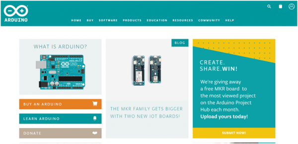
Then click the SOFTWARE on the browse bar, you will have two options ONLINE TOOLS and DOWNLOADS.
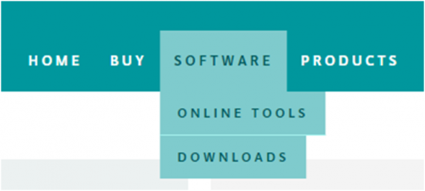
Click DOWNLOADS, it will appear the latest software version of ARDUINO 1.8.5 shown as below.
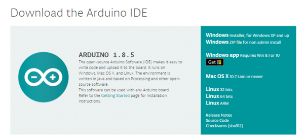
In this software page, on the right side you can see the version of development software for different operating systems. So ARDUINO has a rather powerful compatibility. You should download the software that is compatible with the operating system of your computer.
In our project, we will take WINDOWS system as an example here. There are also two options under Windows system, one is installed version, the other is non-installed version.
For simple installed version, first click Windows Installer, you will get the following page.
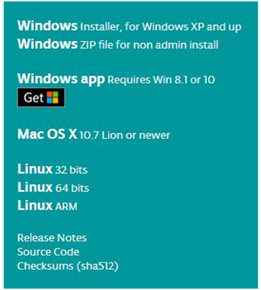

This way you just need to click JUST DOWNLOAD, then click the downloaded file to install it.
For non-installed version, first click Windows ZIP file, you will also get the pop-up interface as the above figure.
Click JUST DOWNLOAD, and when the ZIP file is downloaded well to your computer, you can directly unzip the file and then click the icon of ARDUINO program to start it.
Installing Arduino (Windows)
Install Arduino with the exe. Installation package
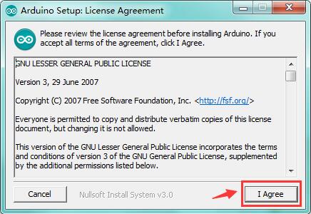
Click“I Agree”to see the following interface.
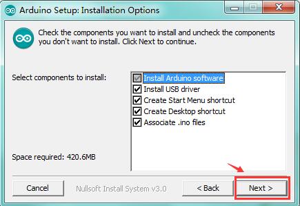
Click “Next”. Pop up the interface below.
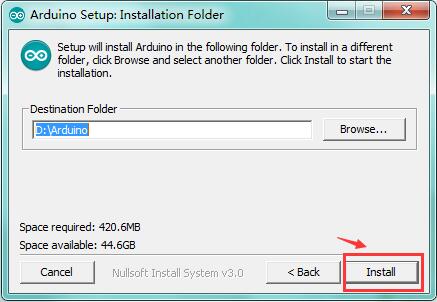
You can press Browse… to choose an installation path or directly type in the directory you want.
Then click “Install” to initiate installation.
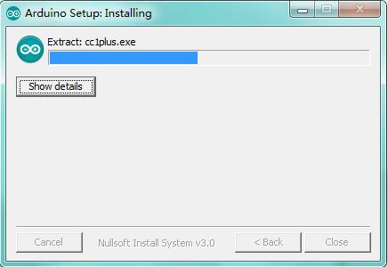
Wait for the installing process, if appear the interface of Window Security, just continue to click Install to finish the installation.
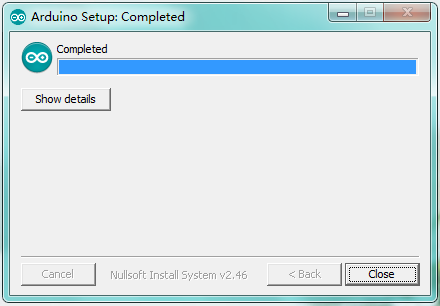
All right, up to now, you have completed the Arduino setup! The following icon will appear on your PC desktop.
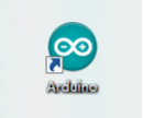
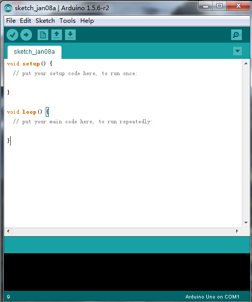
Double-click the icon of Arduino to enter the desired development environment shown as below.
Installing Driver
Next, we will introduce the driver installation of UNO R3 development board. The driver installation may have slight differences in different computer systems. So in the following let’s move on to the driver installation in the WIN 7 system.
The Arduino folder contains both the Arduino program itself and the drivers that allow the Arduino to be connected to your computer by a USB cable. Before we launch the Arduino software, you are going to install the USB drivers.
Plug one end of your USB cable into the Arduino and the other into a USB socket on your computer.
When you connect UNO board to your computer at the first time, right click the icon of your “Computer” —>for “Properties”—> click the “Device manager”, under “Other Devices”, you should see an icon for“Unknown device” with a little yellow warning triangle next to it. This is your Arduino.
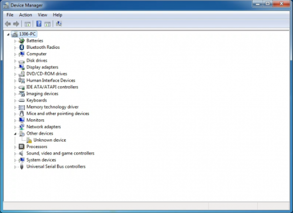
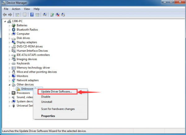
Then right-click on the device and select the top menu option (Update Driver Software...) shown as the figure below..
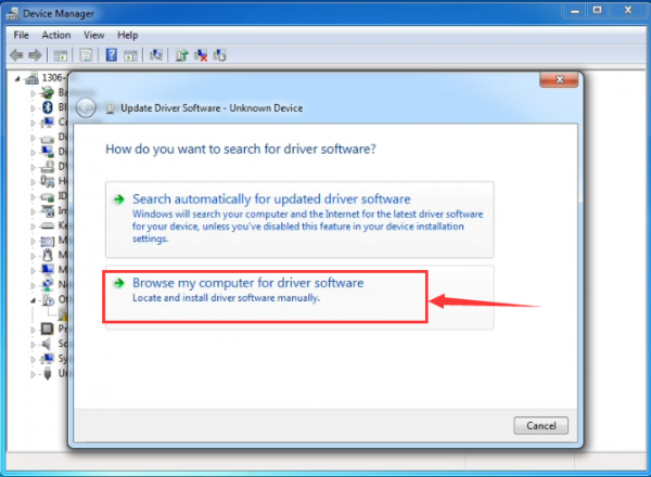
It will then be prompted to either “Search Automatically for updated driversoftware” or “Browse my computer for driver software”. Shown as below. In this page, select “Browse my computer for driver software”.
After that, select the option to browseand navigate to the “drivers” folder of Arduino installation.
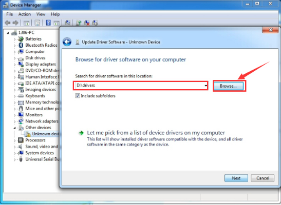
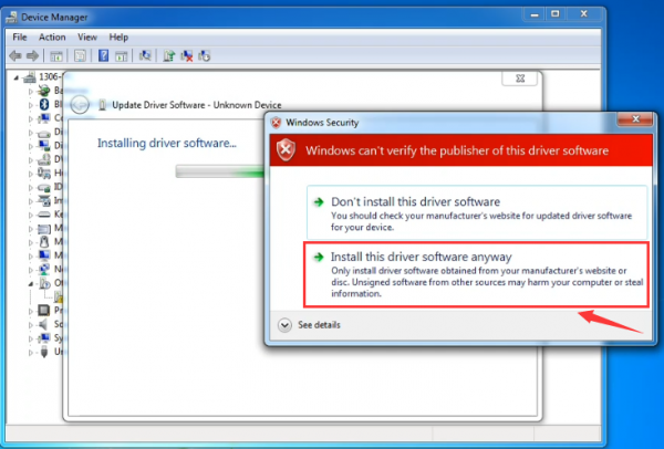
Click “Next” and you may get a security warning, if so, allow the software to be installed. Shown as below.
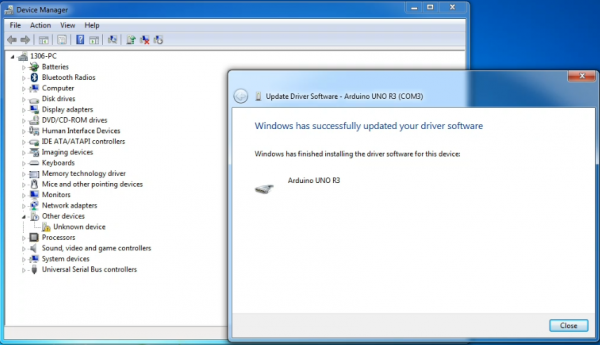
Once the software has been installed, you will get a confirmation message. Installation completed, click “Close”.
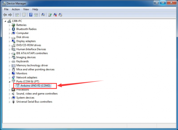
Up to now, the driver is installed well. Then you can right click “Computer” —>“Properties”—>“Device manager”, you should see the device as the figure shown below.
2) Example Use of ARDUINO IDE
STEP 1: Open Arduino
In the previous, we have introduced the driver installation of UNO R3 development board. So this time let’s first have basic understanding of the development environment of ARDUINO. After master that, we are about to upload the program to Arduino board.
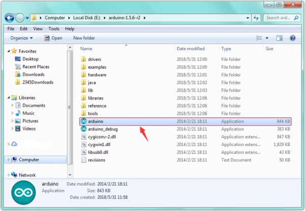
First of all, open the unzipped folder of ARDUINO development software and click icon of ARDUINO to open the software, as the figure shown below.
STEP 2: Build Projects
When open the Arduino software, you will have two options as below:
- Build a new project
- Open an exiting project example
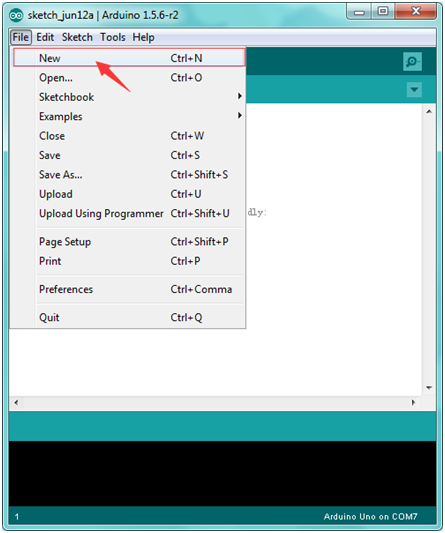
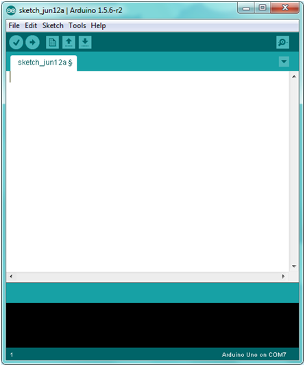
If you want to build a new project, please select “File”→then click “New”, you will see the software interface as follows.
![]()
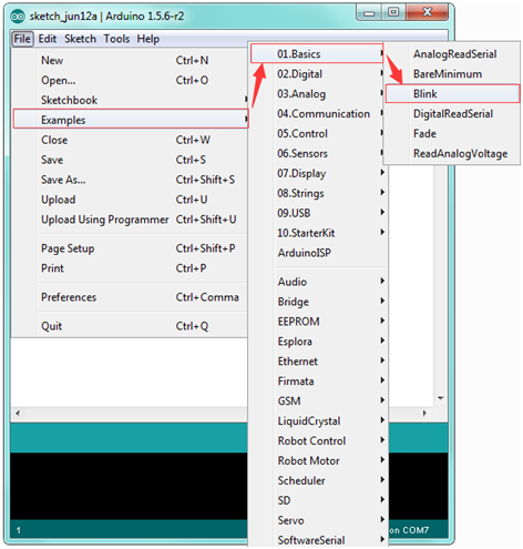
If you want to open an example project, please select File→Example→Basics→Blink. Shown below.
![]()
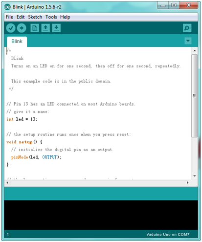
STEP 3: Select Arduino Board
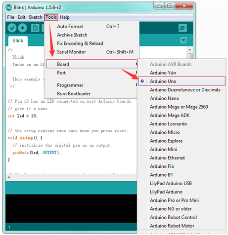
In order to avoid any mistakes during the process of uploading the code to the board, you must first select the correct Arduino board that matches the board connected to your computer.
Or you can directly open the Control Panel of your computer, then click to open Device Manager, you can check your board and port here. Shown as below.
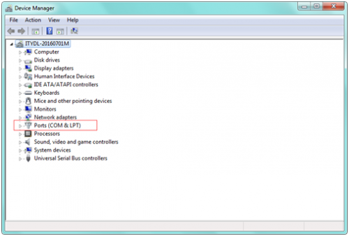
Then come back to the Arduino software, you should click Tools→Board , select the correct board. Here in our tutorial we should select Arduino Uno. Shown as below.
STEP 4: Select Serial Port
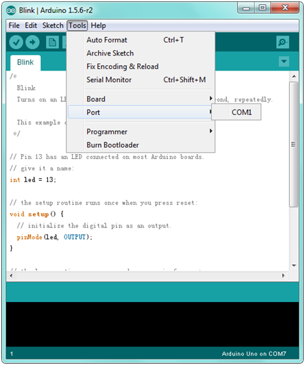
Next, we should select the serial device of Arduino board. You can click Tools→Serial Port. It may be COM3 or higher (COM1 and COM2 are usually reserved as hardware serial port). If you want to find out your Arduino board, you could disconnect your Arduino board, then reopen the menu, you will see the Arduino board disappear. After that reconnect the board and select the serial port.
You should select the correct Serial port that matches the port showed on the Device Manager of your computer.
The figure shown below is only for your reference.
Attach your Arduino board to your computer with the USB cable and check that the “Board Type” and “Serial Port” are set correctly.
STEP 5: Upload the Code to Your Board
Before showing you how to upload the code to your board, first of all let me introduce the function of each icon on the Tool bar of Arduino IDE. Look at the picture showed below.
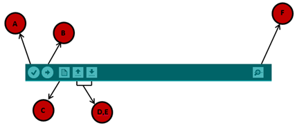
A- Used to verify whether there is any compiling mistakes or not.
B- Used to upload the sketch to your Arduino board.
C- Used to create shortcut window of a new sketch.
D- Used to directly open an example sketch.
E- Used to save the sketch.
F- Used to send the serial data received from board to the serial monitor.
3) Light up an LED
Overview:
In the above courses, you have learned how to use the development software. So want to try it out with an example project? Well, let’s do it right now. Getting started with one more basic program, bring you enter the wonderful programming world of ARDUINO. Cheerful? Great, follow the project process below to have your first try! It is really awesome.
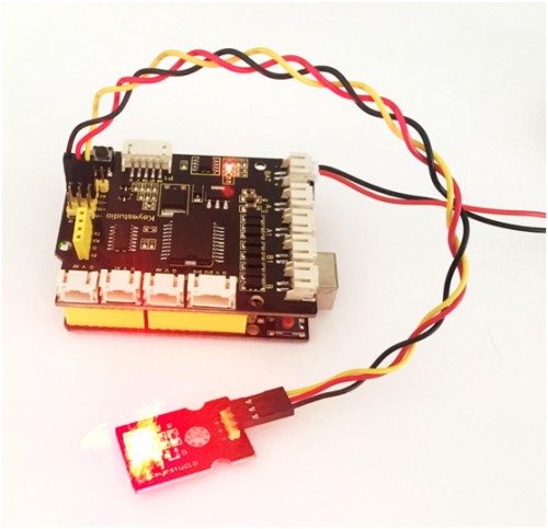
LED experiment is one of the more basic experiments in learning ARDUINO. Here we will use our keyestudio LED module. On the module, you will see a light emitting diode (LED), which has two states of on and off. Since our module itself has done well the circuit, you can use it in a simple way. Just need to connect its pins. There are three lead-out pins on the module, respectively negative pin(marked -), positive pin(marked +) and signal pin(marked S). Note that the modules from different manufactures may have different pin labels.
Next, connect the three pins of LED module to the shield of keyestudio UNO R3 board using three dupont jumper wires. Connect negative pin to the ground, positive pin to 5V, and signal pin to Digital 11. Shown as below.
Test Code 1::
int ledpin=11;// define the LED pin as Digital 11
void setup()
{  pinMode(11, OUTPUT); // initialize digital pin 11 as an output.
}
void loop()
 {
  digitalWrite(11, HIGH);   // turn the LED on (HIGH is the voltage level)
  delay(1000);              // wait for a second
  digitalWrite(11, LOW);    // turn the LED off by making the voltage LOW
  delay(1000);              // wait for a second
}
Note: in the code pay attention to Single line comment (//),so that your can know how your program works.
Comments are lines in the program that are used to inform yourself or others about the way the program works. They are ignored by the compiler, and not exported to the processor, so they don’t take up any space in the microcontroller’s flash memory. Comments' only purpose is to help you understand (or remember), or to inform others about how your program works.
What you should see? Done wiring, compile the code and then click on the 'Upload' button. The second button from the left on the toolbar of Arduino IDE. When upload well the code to the board, you will see the status at the bottom of window will change to “Done uploading”.
Eventually, you will see the LED light up for one second, then off one second. Congrats! Your first programming is done successfully.
4) LED Brightness Controlled by PWM
Overview:
In the previous project, you have learned how to turn on or off an LED. So this time, you may be interested in changing the brightness of an LED light, just making it like the bedside lamp in your bedroom.
Well, so how to do that? Here it is indeed important for you to master the knowledge of PWM. Right, PWM is short for Pulse Width Modulation. How can it be understood in a simple way? We all know that the voltage output of Arduino Digital port only has two states, LOW and HIGH, corresponding to the voltage output of 0V and 5V. If merely make use of LOW and HIGH state, it cannot control the brightness of an LED light. However, if convert the voltage output of 0 Volts and 5 Volts into the value within 0-255, this way you can change the value within 0-255 to control the brightness of light. It is much more feasible, isn’t it ?
Pulse Width Modulation, or PWM, is a technique for getting analog results with digital means. Digital control is used to create a square wave of different duty cycle, a signal switched between on and off. This on-off pattern can simulate voltages in between full on (5 Volts) and off (0 Volts) by changing the portion of the time the signal spends on versus the time that the signal spends off.
The Arduino controller has totally 6 PWM outputs, which are Digital 3, 5, 6, 9, 10 and 11. Shown as follows.
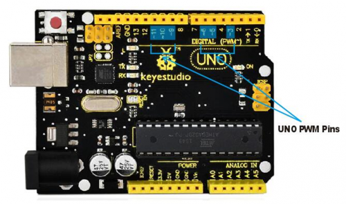
These pins can be used as Digital output or Analog output. If used as Analog output, it needs to call the analogWrite() function of ARDUINO, and this analogWrite() function can be controlled in the range of 0-255.
In the graphic below, the green lines represent a regular time period. This duration or period is the inverse of the PWM frequency. In other words, with Arduino's PWM frequency at about 500Hz, the green lines would measure 2 milliseconds each. A call to analogWrite() is on a scale of 0-255, such that analogWrite(255) requests a 100% duty cycle (always on), and analogWrite(127) is a 50% duty cycle (on half the time) for example.
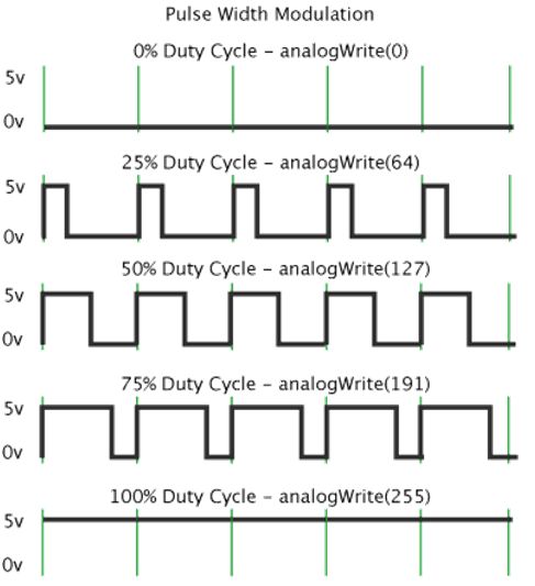
In fact, PWM can be applied to dimming lamps, motor speed, sound production, etc. In the following, we are going to control the brightness of the LED.
Hookup Guide:
On the aspect of hardware, we still utilize the LED connected to D11 mentioned above. You can refer to the wiring diagram as follows:
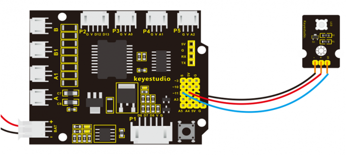
Sample Code 2:
int LED= 11;//define the LED pin
int i = 0;//define a variable i,
void setup(){
pinMode(LED,OUTPUT); //set LED pin as OUTPUT
}
void loop(){
for(i = 0;i < 255;i++){ //variable is changed from 0 to 254(fade in)
analogWrite(LED, i);//set LED brightness
delay(10);//delay 10ms, analogWrite function will be finished in a short time.
//speed is too fast to observe
}
for(i =255;i > 0; i--){ //variable is changed from 255 to 1(fade out)
analogWrite(LED, i);//set LED brightness
delay(10); //delay 10ms
}
}
Code Explanation:
analogWrite(LED, i);
Writes an analog value (PWM wave) to a pin. Can be used to light a LED at varying brightnesses or drive a motor at various speeds. After a call to analogWrite(), the pin will generate a steady square wave of the specified duty cycle until the next call to analogWrite() (or a call to digitalRead() or digitalWrite()) on the same pin. The frequency of the PWM signal on most pins is approximately 490 Hz.
Syntax: analogWrite(pin,value)
It has two parameters:
- pin: the pin to write to. Allowed data types: int.
- value: the duty cycle: between 0 (always off) and 255 (always on). Allowed data types: int
Example Result:
Upload the above code to the board, you could change the LED brightness in the code.
Furthermore, in the motor driving project below, it also involves the concept PWM.
5) Light up LED Matrix
Overview:
In the previous project, we have simply tested the LED. Now we have added a new 8*8 Dot Matrix module to the turtle to show the robot states. Amazing display!
Do you know how is the cool advertising display made? It is exactly composed of these small LED matrix. If you want to make a similar display, this keyestudio 8*8 Dot Matrix modulewill meet you need.
This tiny display has 64 LEDs packed into a 8*8 dot matrix. It integrated HT16K33as driver chip, so with this LED matrix module, you can control it through connecting the I2C communication interfaces ( A4-SDA ; A5-SCL).
It is great for displaying image/text or creating bizarre patterns, and is highly portable and convenient to use. Of course you can program it via IDE or via Mixly block. With just a few steps, you are ready to impress others!
Hookup Guide:
Connect the LED matrix module to the pin header on the motor drive shield. Connect the SCL pin to pin A5, SDA pin to pin A4; Connect VCC pin to 5V, GND to ground.
Sample Code 3:
Code To Note:
In the code, it needs to call three libraries, that is Wire.h; Adafruit_LEDBackpack.hand Adafruit_GFX.h
And Wire.h isa built-in library of Arduino IDE, so not need to add it, but you should place the libraries folder Adafruit_LEDBackpack.hand Adafruit_GFX.hinside the libraries directory of IDE.
Note: place well the libraries folder, need to reopen the Arduino IDE again, and the libraries should be effective.
You can download the libraries from the link below:Note: place well the libraries folder, need to reopen the Arduino IDE again, and the libraries should be effective.
You can download the libraries from the link below:
https://drive.google.com/open?id=16ii-ZQTNK_Fn8KG81rhBw7JX1zQQ6nG6
Place the LED matrix as the left picture shown.
In the experiment, you can control the LED dot matrix display through the code matrix.displaybuffer[0] = B00000011
Note: the number 0 in the matrix.displaybuffer[0] represents the columns of LED. The number 0 is the first column, and the number 1 represents the second column. The rest can be done in the same manner.
B00000011 represents the on and off state of 8 LEDs in the cols. The number 0 represents off, while the number 1 represents on.
So matrix.displaybuffer[0] = B00000011 means that the first column, the LEDs in the row 1, 8, 7, 6, 5, 4 are set to off, the LEDs in the row 3 and 2 are on.
https://drive.google.com/open?id=16ii-ZQTNK_Fn8KG81rhBw7JX1zQQ6nG6
Place the LED matrix as the left picture shown. In the experiment, you can control the LED dot matrix display through the code matrix.displaybuffer[0] = B00000011
Note: the number 0 in the matrix.displaybuffer[0] represents the columns of LED. The number 0 is the first column, and the number 1 represents the second column. The rest can be done in the same manner. B00000011 represents the on and off state of 8 LEDs in the cols. The number 0 represents off, while the number 1 represents on. So matrix.displaybuffer[0] = B00000011 means that the first column, the LEDs in the row 1, 8, 7, 6, 5, 4 are set to off, the LEDs in the row 3 and 2 are on.
